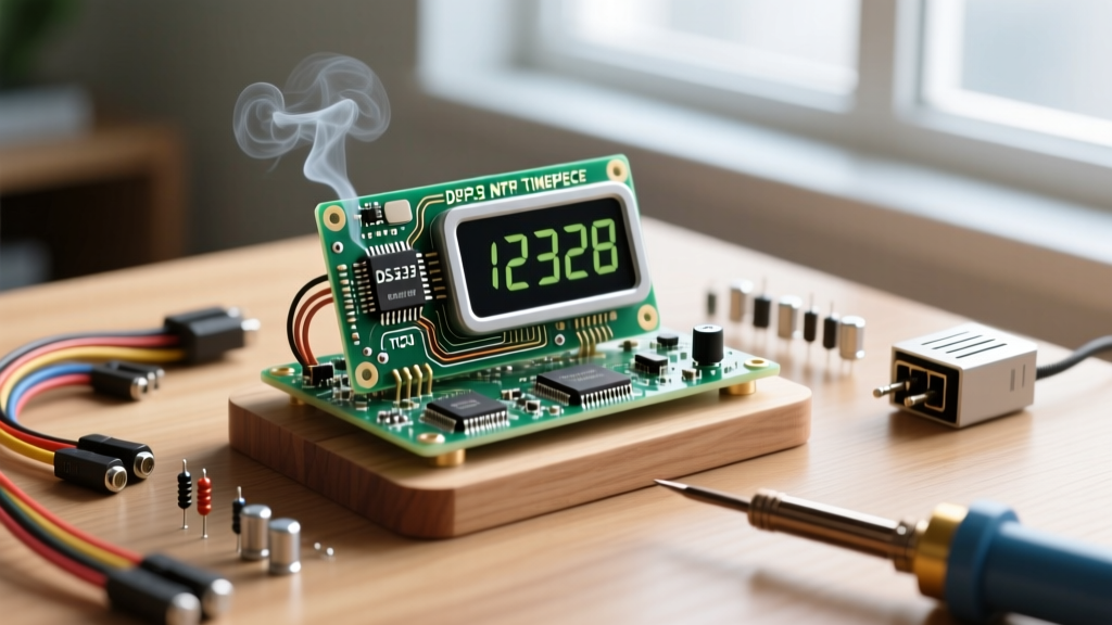

The Evolution of the Maker Timepiece
Building a basic clock with Arduino using an ATmega328P, a DS1307 Real-Time Clock (RTC), and a parallel 16x2 LCD is a foundational rite of passage for electronics hobbyists. However, as maker projects mature, the limitations of this legacy stack become glaringly obvious. The DS1307 relies on a standard 32.768 kHz tuning fork crystal that is highly susceptible to temperature-induced drift, often losing or gaining up to 20 parts per million (ppm). In practical terms, this means your clock could drift by over a minute per month, requiring constant manual recalibration.
As of 2026, the hardware landscape has shifted dramatically. The ESP32-S3 microcontroller offers built-in Wi-Fi for Network Time Protocol (NTP) synchronization at a lower price point than the original Arduino Uno, while modern Temperature Compensated Crystal Oscillator (TCXO) RTCs provide atomic-level precision for offline timekeeping. This migration guide will walk you through upgrading your legacy Arduino clock into a high-precision, NTP-synced ESP32 timepiece, addressing common hardware pitfalls and advanced firmware architectures.
Hardware Migration Matrix: Legacy vs. Modern Stack
Before tearing apart your existing enclosure, it is crucial to understand the component-level upgrades required for a modern timepiece. Below is a comparison of the legacy 2015-era stack versus the recommended 2026 upgrade path.
| Component | Legacy Stack (circa 2015) | Upgraded Stack (2026) | Primary Benefit |
|---|---|---|---|
| MCU | ATmega328P (Arduino Uno) | ESP32-S3-WROOM-1 | Wi-Fi NTP sync, deep sleep capabilities |
| RTC Module | DS1307 (Standard Crystal) | DS3231SN (TCXO) | Drift reduced from 20ppm to <2ppm |
| Display | 16x2 HD44780 (4-bit parallel) | 1.54" GC9A01 TFT or 2.13" e-Paper | High DPI, custom fonts, low power draw |
| Time Source | Manual push-button setting | NTP Pool + RTC Fallback | Zero-touch DST and leap year handling |
| Approx. BOM Cost | $22.00 | $18.50 | Higher performance at lower cost |
RTC Upgrade: Escaping the DS1307 Drift
The core of any reliable offline timepiece is the RTC. The Analog Devices DS3231 integrates a TCXO and a crystal inside a single package. By continuously measuring the internal temperature and adjusting the oscillator frequency via a calibration register, the DS3231SN maintains an accuracy of ±2ppm across a 0°C to +40°C range. This translates to a maximum drift of roughly one minute per year, completely eliminating the need for manual correction between NTP syncs.
CRITICAL WARNING: The ZS-042 Battery Hazard
Most makers purchase the DS3231 on the ubiquitous blue "ZS-042" breakout board. These boards are designed with a charging circuit intended for LIR2032 rechargeable lithium-ion coin cells. However, LIR2032 batteries have a notoriously low capacity (roughly 35mAh) and high self-discharge rates. Most hobbyists naturally swap in a standard, non-rechargeable CR2032 (225mAh).
Danger: If you apply power to a ZS-042 module with a standard CR2032 installed, the board's charging circuit will attempt to charge the non-rechargeable alkaline/lithium cell. This will cause the battery to swell, vent toxic gas, and potentially explode.
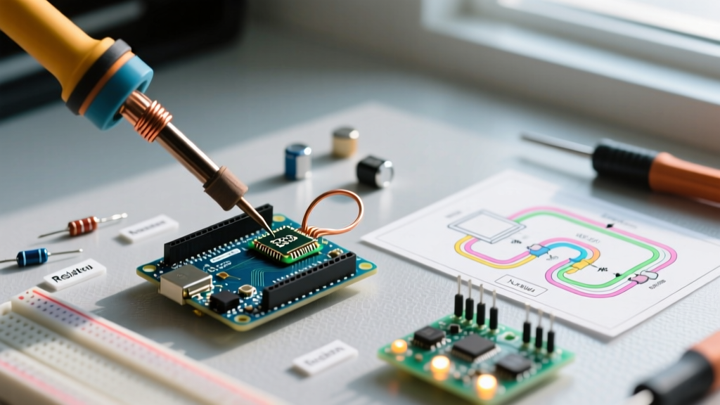
The Fix: Before soldering headers to your ZS-042 module, use a soldering iron and tweezers to desolder and remove the surface-mount diode (usually marked near the battery holder) or the 200Ω SMD resistor that bridges the VCC line to the battery positive terminal. This permanently disables the charging circuit, making the module safe for standard CR2032 batteries and extending offline backup life to over 5 years.
Microcontroller Migration: ATmega328P to ESP32-S3
Migrating from the 5V logic of the ATmega328P to the 3.3V logic of the ESP32-S3 requires attention to I2C pull-up resistors. The DS3231 communicates via I2C (address 0x68). While the ESP32's internal pull-ups are often sufficient for short traces, adding external 4.7kΩ pull-up resistors to the 3.3V line ensures signal integrity, especially when sharing the bus with a display.
Mastering POSIX Timezone Strings
One of the most powerful features of the ESP32 Arduino Core is its native POSIX timezone support via the configTime() function. Instead of writing complex conditional logic to handle Daylight Saving Time (DST) transitions, you pass a standardized POSIX string. For example, to configure US Eastern Time:
configTime(0, 0, "pool.ntp.org", "time.nist.gov");
setenv("TZ", "EST5EDT,M3.2.0,M11.1.0", 1);
tzset();
This string tells the ESP32 that the base offset is 5 hours behind UTC (EST), it observes DST (EDT), and DST begins on the second Sunday of March at 2:00 AM, ending on the first Sunday of November. The Network Time Protocol (NTP) Pool Project provides the global server infrastructure to resolve the initial UTC epoch accurately.
Display Upgrades: Moving Beyond the 16x2 Parallel LCD
The 16x2 HD44780 LCD requires at least 6 GPIO pins for 4-bit parallel communication and consumes roughly 20mA just for the LED backlight. Modern clocks utilize I2C or SPI displays driven by the U8g2 Display Library. U8g2 supports over 1000 display controllers out-of-the-box, including the SSD1306 OLED and the GC9A01 round TFT.
For a premium desk clock aesthetic, consider migrating to a 2.13-inch SPI e-Paper display (like the Waveshare V4 series). E-Paper consumes zero power to maintain an image and only draws ~15mA during a partial refresh. When paired with the ESP32's deep sleep capabilities, you can build a wireless clock that runs for months on a single 18650 lithium-ion cell.
The NTP-to-RTC Fallback Architecture
A robust clock architecture does not rely solely on Wi-Fi; it uses NTP to discipline the local RTC. Implementing this requires a specific boot sequence to minimize network uptime and reduce power consumption.
- Step 1: Cold Boot & RTC Check. The ESP32 wakes and immediately polls the DS3231 via I2C. If the RTC holds a valid epoch (post-2024), the clock immediately renders the time to the display.
- Step 2: NTP Discipline. In the background, the ESP32 connects to Wi-Fi and queries the NTP pool. If the NTP epoch differs from the DS3231 epoch by more than 5 seconds, the ESP32 writes the corrected NTP time back to the DS3231 registers.
- Step 3: SQW Interrupt Setup. Instead of using
delay()ormillis()to track seconds, configure the DS3231's SQW (Square Wave) pin to output a 1Hz interrupt signal. Connect the SQW pin to a GPIO on the ESP32 configured for external wake-up. - Step 4: Deep Sleep Cycle. The ESP32 updates the display, detaches the Wi-Fi modem, and enters deep sleep. The 1Hz pulse from the DS3231 wakes the ESP32 exactly once per second (or once per minute for e-Paper), ensuring the timebase is governed entirely by the hardware TCXO, not the software loop.
Final Calibration and Edge Cases
When upgrading your clock with Arduino frameworks, be mindful of the Y2K38 problem. The standard 32-bit signed integer used for Unix time will overflow on January 19, 2038. Fortunately, the ESP32 Arduino Core (v3.x and later) utilizes 64-bit time_t variables natively, pushing the overflow boundary billions of years into the future. Ensure your RTC library (such as the modernized RTClib by Adafruit) is updated to handle 64-bit epoch conversions to prevent silent rollover bugs in your custom display rendering logic.
By migrating from a legacy ATmega328P and DS1307 stack to an ESP32-S3 and DS3231SN architecture, you transform a basic hobby project into a commercial-grade timepiece capable of self-correction, extreme precision, and ultra-low power consumption.