
Quick Reference: Standard LED Forward Voltage & Resistor Values
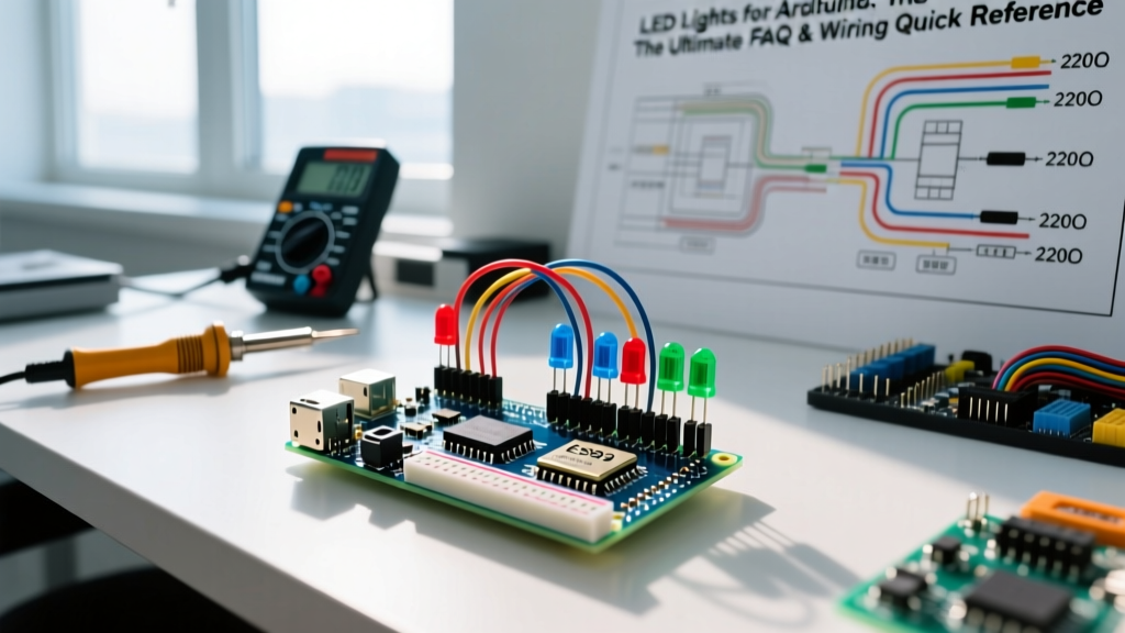
When working with LED lights for Arduino projects, calculating the correct current-limiting resistor is non-negotiable. While the classic 5V Arduino Uno remains popular, the maker landscape in 2026 heavily favors 3.3V logic boards like the Raspberry Pi Pico (RP2040), ESP32-S3, and the Arduino Nano ESP32. Below is a quick-reference matrix for standard 5mm through-hole LEDs targeting a safe 20mA continuous forward current.
| LED Color | Typical Forward Voltage ($V_f$) | Resistor for 5V Logic (Uno/Mega) | Resistor for 3.3V Logic (ESP32/Pico) |
|---|---|---|---|
| Red | 2.0V | 150Ω | 68Ω |
| Yellow | 2.1V | 150Ω | 62Ω |
| Green | 2.2V | 150Ω | 56Ω |
| Blue | 3.2V | 100Ω | Cannot drive directly* |
| White | 3.4V | 82Ω | Cannot drive directly* |
*Note: Blue and White LEDs have a $V_f$ higher than 3.3V. To drive them from a 3.3V microcontroller, you must use a transistor (e.g., 2N2222) or a dedicated LED driver IC powered by a 5V or higher supply rail.
Frequently Asked Questions: Basic Wiring & Power
Do I absolutely need a resistor for standard LEDs?
Yes. An LED is a diode with a non-linear I-V curve. Once the forward voltage threshold is reached, its internal resistance drops to near zero, causing it to draw maximum current from the source until it burns out or damages the microcontroller's GPIO pin. As detailed in Arduino's official guide on LEDs and resistors, using Ohm's Law ($R = (V_{source} - V_f) / I$) ensures the LED operates safely within its 20mA nominal rating.
What are the exact current limits for Arduino GPIO pins?
For the classic ATmega328P (Arduino Uno/Nano), the absolute maximum current per I/O pin is 40mA, but the recommended continuous operating current is 20mA. Furthermore, the total current drawn across all VCC and GND pins combined must not exceed 200mA. If your project requires lighting up 15 standard LEDs simultaneously (15 x 20mA = 300mA), you will exceed the microcontroller's total package limit and risk thermal shutdown or silicon damage. In this scenario, use a ULN2803 Darlington transistor array or a 74HC595 shift register to offload the current to an external power supply.
How does PWM fading work with analogWrite()?
Microcontrollers cannot output true analog voltages on standard digital pins. Instead, the analogWrite() function uses Pulse Width Modulation (PWM) to simulate analog levels by rapidly toggling the pin HIGH and LOW. According to the Arduino analogWrite reference, the default PWM frequency on most ATmega328P pins is approximately 490 Hz. However, pins 5 and 6 on the Uno operate at 980 Hz. If you are multiplexing LEDs or using persistence-of-vision (POV) displays, stick to pins 5 and 6 to avoid visible flickering.
Advanced LED Tech: RGB, Strips, and NeoPixels
Why do my WS2812B NeoPixels flicker or show the wrong colors?
Addressable LED lights for Arduino like the WS2812B (NeoPixel) are notoriously sensitive to signal integrity and power delivery. If your strip is flickering, displaying random colors, or only lighting up the first few pixels, check these three hardware edge cases:
- Logic Level Mismatch: WS2812B data lines require a minimum of 0.7 x $V_{DD}$ to register a logical HIGH. If powering the strip with 5V, the data signal must be at least 3.5V. If you are using a 3.3V board (like an ESP32), the 3.3V data signal will cause intermittent failures. Fix: Use a 74AHCT125 level shifter to boost the 3.3V data signal to 5V, or use the '1N4148 diode trick' (placing a diode on the data line with the cathode facing the LED, and pulling the data line up to 5V via a resistor).
- Missing Capacitor: Sudden color changes (especially to full white) cause massive current spikes that can brown out the LED strip's internal logic. Always place a 1000μF, 6.3V (or higher) electrolytic capacitor across the strip's main power and ground terminals.
- Missing Data Resistor: Place a 300Ω to 500Ω resistor between the microcontroller's data pin and the strip's DIN pin to prevent high-frequency ringing and protect the first pixel's data input.
Pro-Tip from the Adafruit NeoPixel Überguide: Never connect or disconnect NeoPixel strips while they are powered. The inductive kickback and hot-swapping transients can easily fry the data input pin of the first LED in the chain, rendering the entire strip unresponsive.
How do I properly inject power into long LED strips?
A standard WS2812B strip draws roughly 60mA per pixel at full white brightness. A single 1-meter strip (60 LEDs) will pull 3.6 Amps. The copper traces on standard flexible PCB strips are not thick enough to carry this current over long distances without significant voltage drop, leading to dim, red-shifted LEDs at the far end of the strip.
The Rule of Thumb: Inject 5V power at both ends of a 1-meter strip. For strips longer than 2 meters, inject power every 50 to 60 pixels (approximately every 1 meter). Use 18 AWG or thicker silicone wire for the power injection lines, and ensure your 5V power supply is rated for at least 20% more than the calculated maximum current draw.
Troubleshooting Edge Cases & Failure Modes
My LED is dim, even with the correct resistor. What gives?
If your resistor math is correct but the LED is dim, you are likely encountering GPIO current starvation or a wiring fault. Use a digital multimeter to measure the voltage directly at the GPIO pin while the LED is lit. If a 5V pin drops to 4.2V under load, the microcontroller's internal trace resistance is bottlenecking the current. Alternatively, check your breadboard; cheap, oxidized breadboard contacts can introduce 10Ω to 50Ω of parasitic resistance, significantly altering your circuit's total resistance.
What is Charlieplexing and when should I use it?
If you need to control a massive array of standard LEDs but lack the GPIO pins or shift registers, Charlieplexing leverages the tri-state logic (HIGH, LOW, INPUT/High-Z) of microcontroller pins. By wiring LEDs in anti-parallel pairs between pins, you can control $n^2 - n$ LEDs using only $n$ pins. For example, 6 Arduino pins can independently control 30 LEDs. However, Charlieplexing requires complex software matrices and limits the duty cycle, meaning the LEDs will appear dimmer than direct-wired configurations. For most modern makers, using a $2 I2C LED driver like the IS31FL3731 is a far more reliable and cost-effective alternative.
Summary Checklist for 2026 Maker Projects
- Verify Logic Levels: Always confirm if your board is 5V or 3.3V before selecting resistors or addressable strips.
- Protect the MCU: Never exceed 20mA per pin or 200mA total package limit on ATmega328P boards.
- External Power: Use external 5V switching power supplies (like Mean Well LRS series) for any LED project exceeding 10 standard LEDs or 20 addressable pixels.
- Signal Integrity: Keep data wires for addressable LEDs under 50cm, and always use a series resistor and level shifter when crossing voltage domains.