
The Anatomy of an Arduino Output Failure
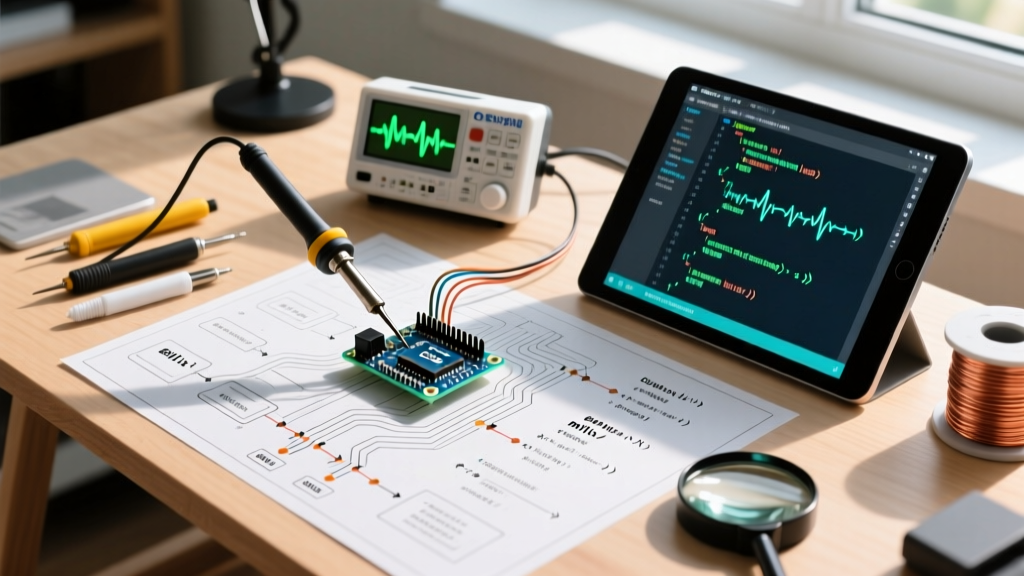
When a project stalls because an Arduino output pin refuses to drive a relay, illuminate an LED, or send a logic signal, the root cause typically falls into one of three categories: software misconfiguration, logic-level mismatch, or catastrophic hardware failure. In 2026, the maker ecosystem is more diverse than ever. While the classic Uno R3 remains a staple, modern boards like the Uno R4 Minima and Nano ESP32 have introduced new microcontroller architectures with vastly different output characteristics. Troubleshooting requires a methodical approach that bridges the gap between your IDE sketch and the physical silicon.
Microcontroller Output Specifications: A 2026 Comparison
Before probing with a multimeter, you must understand the absolute limits of your specific board. Driving a 5V relay coil directly from a Nano ESP32 will not only fail to trigger the relay but will likely destroy the ESP32-S3's internal bond wires due to overcurrent. Below is a critical reference matrix for the most common boards used today.
| Board Model | Core MCU | Logic Level | Safe Max Pin Current | PWM Capable Pins |
|---|---|---|---|---|
| Uno R3 | ATmega328P | 5V | 20 mA | 3, 5, 6, 9, 10, 11 |
| Uno R4 Minima | Renesas RA4M1 | 5V | 8 mA (Ports 1/2) | 3, 5, 6, 9, 10, 11 |
| Nano ESP32 | ESP32-S3 | 3.3V | 10 mA (Strict) | 2-13 (Configurable) |
For deeper silicon-level specifications, always consult the Microchip ATmega328P Specifications or the respective ARM/RISC-V datasheets. Note that while the ATmega328P has an absolute maximum rating of 40mA per pin, sustained operation at this limit causes excessive thermal dissipation inside the IC package, leading to premature latch-up or logic degradation. Always design your output circuits to draw less than 50% of the absolute maximum rating.
Phase 1: Diagnosing Digital Output (HIGH/LOW) Failures
If your digital output is completely unresponsive, follow this diagnostic sequence to isolate the fault domain.
1. The 'Floating Pin' Illusion (Software Domain)
The most common reason for a dead Arduino output is forgetting to declare the pin mode. By default, all microcontroller pins boot into a high-impedance INPUT state. If you call digitalWrite(8, HIGH); without first calling pinMode(8, OUTPUT);, the pin will not source current. Instead, it may weakly activate the internal pull-up resistor (typically 20kΩ to 50kΩ). When measured with a high-impedance digital multimeter (DMM), this floating state can display a 'ghost voltage' of 1.2V to 2.5V, tricking beginners into thinking the pin is partially working. Always verify your setup block against the official Arduino pinMode Reference.
2. The USB Polyfuse Voltage Sag (Power Domain)
If your Arduino output measures 4.2V instead of the expected 5.0V when set to HIGH, your board's power rail is sagging. The classic Uno R3 features a 500mA PTC resettable polyfuse on the USB VBUS line. If your project draws 300mA through the 5V pin (e.g., powering a string of WS2812B LEDs), the polyfuse heats up, its resistance spikes, and the 5V rail collapses. The Fix: Bypass the USB power entirely by supplying 7V-9V through the barrel jack or Vin pin, utilizing the onboard NCP1117 linear regulator, or inject regulated 5V directly into the 5V pin (bypassing the polyfuse, though this removes USB overcurrent protection).
3. Logic Level Incompatibility (Hardware Domain)
If you are using a 3.3V board like the Nano ESP32 or Nano 33 IoT to drive a 5V logic component (like an older HC-SR04 ultrasonic sensor or a 5V TTL display), the 3.3V HIGH output may fall below the target device's V_IH (Input High Voltage) threshold. The target device simply ignores the signal. The Fix: Insert a bidirectional logic level shifter (e.g., Texas Instruments TXS0108E or a cheap MOSFET-based breakout) between the Arduino output and the 5V load.
Phase 2: Troubleshooting PWM (Analog Output) Anomalies
Pulse Width Modulation (PWM) allows you to simulate analog voltages by rapidly toggling a digital output. However, PWM failures are notoriously difficult to debug with a standard multimeter, which will only show an average DC voltage.
The 490Hz vs 980Hz Frequency Trap
Not all PWM pins are created equal. On the ATmega328P (Uno R3), pins 5 and 6 are tied to Timer0, which operates at approximately 980Hz. Pins 3, 9, 10, and 11 are tied to Timer1 and Timer2, operating at roughly 490Hz. If you are using PWM to drive a DC motor via an H-bridge and you accidentally use pin 5, the 980Hz frequency might cause excessive switching losses and heat in your MOSFETs compared to the 490Hz pins. Consult the Arduino analogWrite Reference to map your timers correctly.
Pro-Tip for Audio Projects: If you are using PWM to generate audio tones via a low-pass filter, the default 490Hz carrier frequency will introduce severe audible whining. You must manually reconfigure the Timer1 prescaler registers in your setup function to push the PWM frequency above 20kHz (the limit of human hearing) before applying analogWrite().Diagnosing PWM with an Oscilloscope
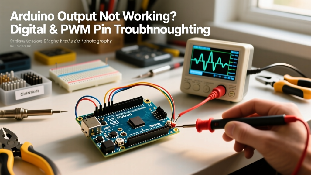
If your motor is stuttering or your LED is flickering instead of dimming smoothly, your PWM signal is likely malformed. Connect a logic analyzer (like the Saleae Logic Pro 8) or a basic digital storage oscilloscope (DSO) to the pin.
What to look for:
- Duty Cycle Accuracy: At
analogWrite(pin, 127), the pulse width should be exactly 50% of the period. - Rise/Fall Times: If the square wave looks like a shark fin (slow rise time), your output pin is heavily capacitively loaded. You are likely driving a long cable or a high-capacitance MOSFET gate directly. Add a dedicated gate driver IC (like the TC4427) to buffer the Arduino output.
Phase 3: Hardware Damage and Pin Protection
If you have verified the code, confirmed the logic levels, and the pin still outputs 0V (or is stuck at VCC), the silicon is likely dead. Microcontroller pins are fragile. Here are the most common ways an Arduino output is destroyed in the field, and how to prevent it.
1. Inductive Kickback (The Flyback Diode Rule)
Connecting a relay coil, solenoid, or DC motor directly to an Arduino output pin is a guaranteed way to kill the microcontroller. When the output transitions from HIGH to LOW, the collapsing magnetic field in the inductive load generates a massive reverse voltage spike (often exceeding 50V). This spike punches through the pin's internal ESD protection diodes, permanently shorting the pin to ground. The Fix: Never drive inductive loads directly. Use a logic-level N-channel MOSFET (like the IRLZ44N) or an NPN transistor (2N2222), and always place a 1N4007 flyback diode in reverse parallel across the coil.
2. Hot-Swapping and Ground Loops
Plugging in a sensor or actuator while the Arduino is powered (hot-swapping) can cause transient ground bounces. If the ground potential of the external device is slightly higher than the Arduino's ground, current will flow backward through the Arduino output pin's protection network. In industrial or automotive environments, always use digital isolators (like the ADuM1201) or optocouplers (like the PC817) to physically break the electrical connection between the Arduino output and the high-noise environment.
Summary Diagnostic Checklist
- Verify Code: Ensure
pinMode(pin, OUTPUT)is present in thesetup()loop. - Measure Unloaded: Disconnect all external components. Measure the pin voltage with a DMM. It should read 0.0V (LOW) or ~4.8V-5.0V (HIGH).
- Check Power Rail: Measure the 5V and 3.3V pins on the board header. If they are sagging below 4.5V or 3.1V respectively, your power supply is insufficient.
- Verify Logic Thresholds: Ensure your target component accepts the voltage level (3.3V vs 5V) provided by your specific board.
- Inspect for Heat: Touch the microcontroller IC. If it is too hot to keep your finger on, you have a short circuit or severe overcurrent condition on an output pin.
By understanding the physical limitations of the silicon and the electrical realities of your external components, you can systematically eliminate variables and restore your Arduino output to full functionality. Whether you are toggling a simple GPIO on an Uno R4 or generating high-speed PWM on a Nano ESP32, respecting the datasheet limits is the hallmark of a reliable embedded systems designer.