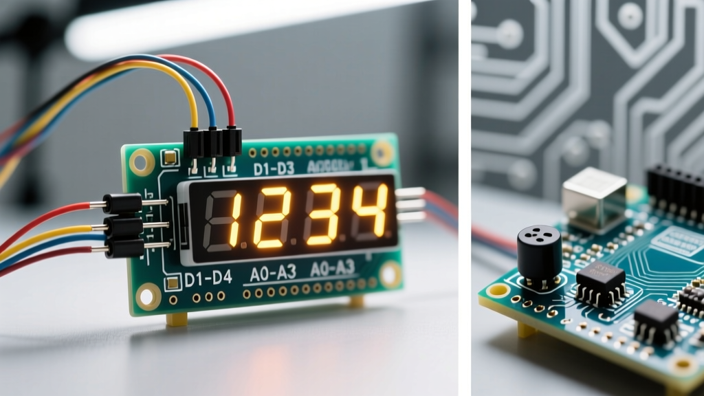

The Anatomy of an Arduino 4 Digit 7 Segment Display
When integrating an Arduino 4 digit 7 segment display into a maker project, you are essentially dealing with 28 individual LEDs (four sets of seven segments, plus four decimal points) crammed into a single, compact package. If each LED required its own dedicated microcontroller pin, you would need 32 I/O pins—far exceeding the capacity of a standard ATmega328P-based board. Instead, manufacturers use a shared pin architecture, typically resulting in a 12-pin module.
These 12 pins are divided into two categories:
- Segment Pins (8): These control the specific LED bars (labeled A through G, plus the Decimal Point). They are shared across all four digits.
- Common/Digit Pins (4): These act as the ground or power source for each individual digit (Digit 1 through Digit 4).
Before wiring anything, you must determine if your specific module is Common Anode or Common Cathode. In a Common Anode display, the digit pins connect to 5V, and you sink current through the segment pins to illuminate them. In a Common Cathode display, the digit pins connect to Ground, and you source current from the segment pins. The 2026 market is flooded with cheap, unmarked displays from overseas suppliers, so always verify your pinout with a multimeter's diode-test mode before applying power.
The Magic of Multiplexing: Persistence of Vision
Because the segment pins are shared, you cannot physically light up two different numbers simultaneously. If you apply power to Digit 1 and Digit 2 at the same time, and set segment 'A' high, both digits will display 'A'. To show a multi-digit number like '1234', we use a technique called time-division multiplexing.
Multiplexing exploits the human eye's Persistence of Vision (POV). The microcontroller illuminates only one digit at a time, cycling through all four digits so rapidly that the brain perceives them as being lit continuously. To achieve a flicker-free display, the entire 4-digit cycle must complete at least 60 times per second (60Hz refresh rate). This means each individual digit is turned on and off every 4 milliseconds.
The Transistor Trap: Why Beginners Fry Their Arduino Pins
This is where 90% of online tutorials fail, leading to destroyed microcontrollers. Let us look at the math for a standard red 7-segment display.
Ohm's Law Calculation for Segment Resistors:
Arduino Output: 5V
LED Forward Voltage (Vf): 2.0V
Target Current: 15mA per segment
Resistor = (5V - 2.0V) / 0.015A = 200Ω (Use 220Ω standard value).
If you use 220Ω resistors on the 8 segment pins, each segment draws roughly 13.6mA. If you display the number '8' (which lights up 7 segments), the total current flowing through the active Common Digit Pin is 7 × 13.6mA = 95.2mA.
The absolute maximum current rating for a single I/O pin on the ATmega328P is 40mA, with a recommended operating limit of 20mA. Pushing 95mA through a single Arduino pin will cause thermal runaway and permanently destroy the pin's internal output buffer. You must use transistors to switch the Common Digit pins.
Transistor Selection and Wiring
For a Common Cathode display, use NPN transistors (like the BC547 or 2N2222) to sink the digit pins to ground. For a Common Anode display, use PNP transistors (like the BC557) to source 5V to the digit pins. Always place a 1kΩ base resistor between the Arduino I/O pin and the transistor base to limit base current.
Bare Multiplexed Displays vs. TM1637 Driver Modules
In 2026, makers have a distinct choice between wiring bare 12-pin displays or using dedicated driver ICs like the TM1637. Here is how they compare for modern prototyping:
| Feature | Bare 12-Pin Display (Multiplexed) | TM1637 Driver Module |
|---|---|---|
| Average Cost (2026) | $1.20 - $1.80 (plus transistors/resistors) | $2.00 - $3.50 (fully assembled PCB) |
| Wiring Complexity | High (12+ wires, breadboard clutter) | Low (4 wires: VCC, GND, CLK, DIO) |
| Arduino Pins Used | 12 Digital I/O pins | 2 Digital I/O pins |
| CPU Overhead | High (Requires constant timer interrupts) | Near Zero (IC handles multiplexing) |
| Brightness Control | Hardware PWM required on segment pins | Software command via I2C-like protocol |
If you are building a commercial product or a complex robot where CPU cycles are precious, the TM1637 is superior. However, understanding bare multiplexing remains a critical rite of passage for mastering microcontroller timing and hardware constraints.
Step-by-Step Wiring Guide (Common Cathode with NPN Transistors)
Below is a robust, safe wiring matrix for a generic 5641AS Common Cathode display using four BC547 NPN transistors. This setup guarantees you will never exceed the Arduino's per-pin current limits.
| Display Pin | Function | Arduino / Hardware Connection |
|---|---|---|
| 11, 7, 4, 2 | Segments (A, B, C, D) | Pins 6, 7, 8, 9 (via 220Ω resistors) |
| 1, 10, 5, 3 | Segments (E, F, G, DP) | Pins 10, 11, 12, 13 (via 220Ω resistors) |
| 12 | Digit 1 (Common) | BC547 Collector (Base to Arduino Pin 2 via 1kΩ) |
| 9 | Digit 2 (Common) | BC547 Collector (Base to Arduino Pin 3 via 1kΩ) |
| 8 | Digit 3 (Common) | BC547 Collector (Base to Arduino Pin 4 via 1kΩ) |
| 6 | Digit 4 (Common) | BC547 Collector (Base to Arduino Pin 5 via 1kΩ) |
Note: All four BC547 Emitter pins connect directly to the Arduino GND rail.
Non-Blocking Code Architecture Using millis()
The most common mistake when coding an Arduino 4 digit 7 segment display is using the delay() function to time the multiplexing. If you use delay(5) to wait between digit switches, your microcontroller is entirely blocked. It cannot read sensors, process button presses, or handle serial communication while delaying. This results in a sluggish, unresponsive project.
Instead, you must implement a non-blocking state machine using the millis() function. As detailed in the official Arduino BlinkWithoutDelay tutorial, this allows the CPU to handle display refreshes in the background while executing your main logic loop.
Furthermore, managing time-based events without blocking is thoroughly documented in the Arduino millis() reference. By checking if a specific interval has passed (e.g., 2 milliseconds), you can increment an index variable from 0 to 3, updating the active digit pin and pushing the corresponding segment data to the shift registers or direct I/O pins.
Troubleshooting: Ghosting and Flicker
Even with perfect wiring, software timing errors can cause visual artifacts. Here is how to diagnose and fix the two most common issues:
1. The 'Ghosting' Effect
Ghosting occurs when faint segments from the previous digit bleed into the current digit. This happens because microcontroller I/O pins do not change state instantaneously. If you switch the active Common Digit pin before the Segment pins have fully discharged, the brief overlap causes a faint glow on the wrong digit.
The Fix: Implement a 'blanking' phase in your code. The sequence must be: 1. Turn OFF all segment pins. 2. Turn OFF the current Common Digit pin. 3. Turn ON the next Common Digit pin. 4. Turn ON the new segment pins.
2. Low-Refresh Flicker
If your display looks like it is vibrating or flickering, your multiplexing refresh rate has dropped below 50Hz. This is almost always caused by blocking code elsewhere in your loop(). If you are reading a slow I2C sensor (like a BME280) that takes 15ms to return data, your display will freeze during that read, causing a visible stutter.
The Fix: Move sensor readings to a much slower, non-blocking interval (e.g., read the sensor every 500ms), or utilize hardware interrupts and Timer1 libraries to handle the display multiplexing entirely independent of the main loop() execution.
Summary
Mastering the Arduino 4 digit 7 segment display requires moving beyond simple plug-and-play logic. By understanding the physical limits of the ATmega328P, utilizing external transistors for safe current sinking, and writing non-blocking multiplexing routines, you transform a fragile, flickering prototype into a robust, professional-grade instrument panel. For deeper dives into LED physics and forward voltage characteristics, the SparkFun Seven Segment Display Tutorial remains an excellent foundational resource.