
Introduction to the STM32H747XI Powerhouse
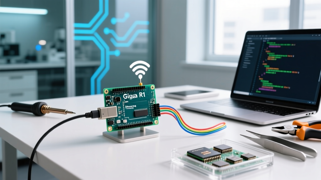
The Arduino Giga R1 WiFi (Model ABX00063) represents a critical bridge between the legacy I/O density of the Mega2560 and the high-end processing muscle of the Portenta H7. Built around the STMicroelectronics STM32H747XI dual-core microcontroller, it features a 480 MHz Cortex-M7 and a 240 MHz Cortex-M4. As of 2026, it remains the premier choice for edge AI, complex DSP (Digital Signal Processing), and multi-threaded IoT gateways, priced at approximately $92 USD.
However, the Giga R1 is not a simple plug-and-play board. Its dual-core architecture, Mbed OS foundation, and specialized power delivery network require precise configuration to avoid bricking, memory faults, or peripheral contention. This guide details the exact hardware and software configuration steps required to deploy the Giga R1 in production and advanced maker environments.
Hardware Prerequisites and Power Delivery Configuration
Before uploading a single sketch, you must understand the Giga R1 power topology. A common failure mode for beginners is frying the onboard step-down converter by misunderstanding the Vin pin.
- USB-C Power Delivery (PD): The board utilizes an STUSB4500 USB-C PD controller. It automatically negotiates 5V at up to 3A when connected to a compliant PD charger. Always use a high-quality USB-C cable rated for 3A to prevent voltage drops during Wi-Fi transmission spikes.
- Barrel Jack (5.5x2.1mm): Accepts 5V to 12V DC. The recommended input is 5V/2A or 7V/1A. The onboard MP2322 step-down converter handles the regulation.
- The Vin Pin Trap: Unlike older AVR boards, the Vin pin on the Giga R1 is NOT a regulated 5V output. It is directly tied to the barrel jack input. If you power the board via USB-C and attempt to draw 5V from Vin to power external sensors, you will experience brownouts. Use the dedicated 5V pin for regulated output, keeping total draw under 800mA to avoid thermal throttling of the onboard LDO.
Expert Warning: Supplying more than 12V to the barrel jack or Vin pin will instantly destroy the MP2322 regulator and potentially backfeed into the STM32H747XI, permanently bricking the MCU. Always verify your bench power supply limits before connecting.
Arduino IDE Core Installation and Memory Partitioning
The Giga R1 relies on the Arduino Mbed OS Giga Boards core. As of 2026, Arduino IDE 2.x and 3.x handle this seamlessly, but manual flash partitioning is required for dual-core deployments.
- Open the Boards Manager and search for
Arduino Mbed OS Giga Boards. Install the latest stable release (v4.x or higher). - Select Arduino Giga R1 WiFi from the board dropdown.
- Navigate to Tools > Flash Split. By default, the 2MB internal flash is allocated entirely to the M7 core. To utilize the M4, you must select a split configuration (e.g., 1MB M7 + 1MB M4).
- Under Tools > USB Stack, ensure USB HID or CDC is selected based on your peripheral needs. The default Mbed USB stack is sufficient for standard serial debugging.
For comprehensive pinout and schematic details, always refer to the official Arduino Giga R1 Documentation.
Dual-Core Architecture: Cortex-M7 and Cortex-M4 Orchestration
The true power of the Giga R1 lies in asymmetrical multiprocessing (AMP). The Cortex-M7 should handle heavy computational tasks (e.g., TensorFlow Lite Micro inference, FFT calculations, and Wi-Fi stack management), while the Cortex-M4 handles deterministic, real-time I/O (e.g., reading high-speed encoders, PWM generation, and interrupt servicing).
Communication between the cores is managed via the RPC (Remote Procedure Call) library, which abstracts the OpenAMP inter-processor communication protocol.
Configuring the RPC Link
To call a function on the M4 from the M7, you must define the RPC interface on both cores. Below is the structural logic for an M4 sensor-reading slave:
// M4 Core Sketch (Sensor Slave)
#include <RPC.h>

int readHighSpeedSensor() {
  // Read from ADC or I2C with strict timing
  return analogRead(A0);
}

void setup() {
  RPC.begin();
  RPC.bind("readSensor", readHighSpeedSensor);
}

void loop() {
  // M4 stays in low-power or handles strict RTOS tasks
}
On the M7 side, you invoke this via RPC.call("readSensor").as<int>(). This prevents the M7 Wi-Fi stack interrupts from causing jitter in your M4 sensor sampling.
Murata 1DX Wi-Fi and Bluetooth Firmware Configuration
The Giga R1 features a Murata 1DX module based on the Cypress CYW4343W chipset, supporting 802.11b/g/n and Bluetooth 4.1. A frequent configuration error is attempting to use the WiFi.h library without first ensuring the Wi-Fi firmware is flashed and matched to the Mbed core version.
In earlier years, users relied on the WiFiFirmwareUpdater sketch. In 2026, this is deprecated. The correct methodology is using the arduino-fwuploader CLI tool or the IDE's built-in flasher.
- Step 1: Install the
arduino-fwuploadervia the Arduino CLI or download the binary from the Arduino GitHub repository. - Step 2: Put the board into bootloader mode (double-tap the reset button; the green LED will pulse).
- Step 3: Run the command:
arduino-fwuploader flash --fqbn arduino:mbed_giga:giga --port /dev/ttyACM0(adjust port for Windows/Mac).
Failure to match the firmware binary to the Mbed OS core version will result in the WiFi.begin() function hanging indefinitely or returning a WL_CONNECT_FAILED status code.
Comparison Matrix: Giga R1 vs. Portenta H7 vs. Teensy 4.1
When designing a custom PCB or selecting a dev board for a 2026 production run, understanding the trade-offs between high-end MCUs is critical.
| Feature | Arduino Giga R1 WiFi | Arduino Portenta H7 | Teensy 4.1 |
|---|---|---|---|
| MCU Core | STM32H747XI (M7 + M4) | STM32H747XI (M7 + M4) | NXP i.MX RT1062 (M7) |
| Max Clock | 480 MHz | 480 MHz | 600 MHz |
| Wireless | Murata 1DX (Wi-Fi/BT) | Murata 1DX (Wi-Fi/BT) | None (Requires external SPI) |
| Form Factor | Mega2560 Compatible | Portenta High-Density | Teensy Custom |
| Approx. Price (2026) | $92 USD | $115 USD | $42 USD |
| Best Use Case | IoT Gateways, Legacy Shields | Industrial Edge AI, Vision | High-Speed DSP, Audio |
Critical Failure Modes and DFU Recovery
Because the Giga R1 uses the Mbed OS bootloader, writing a sketch that blocks the USB stack or corrupts the memory map can make the board disappear from your OS device manager. Do not panic; the hardware is rarely damaged.
The Double-Tap DFU Reset
If the board fails to enumerate via USB:
- Locate the red RESET button near the USB-C port.
- Tap the button twice in rapid succession (within 500ms).
- The onboard green LED will begin to pulse (fade in and out). This indicates the STM32 has entered its native ROM DFU (Device Firmware Upgrade) bootloader mode, bypassing the corrupted Mbed user flash.
- The board will appear in your OS as
STM32 BOOTLOADER(VID: 0483, PID: DF11). - Use the Arduino IDE to upload a known-good sketch (like
Blink), ensuring you select the correct DFU port in the IDE port menu.
Recovering from M4/M7 Flash Contention
If you incorrectly partition the flash and overwrite the M4 bootloader region while flashing the M7, the board may hard-fault on boot, drawing excessive current (spiking to 600mA+ on USB). To resolve this, you must perform a mass erase via STMicroelectronics' STM32CubeProgrammer. Connect via the DFU bootloader, select Full Flash Erase, and then re-flash the Arduino Mbed bootloader binary available on the STMicroelectronics STM32H747XI product page or via the Arduino IDE's Burn Bootloader function (requires an external SWD programmer like the ST-Link V2 connected to the Giga's dedicated SWD header).
Final Deployment Considerations
When moving from the breadboard to a custom PCB using the Giga R1 as a System-on-Module (SOM), remember that the Murata 1DX antenna requires a strict RF keep-out zone. Maintain a 15mm clearance around the antenna trace on the bottom-right corner of the board to prevent Wi-Fi signal attenuation. Furthermore, ensure your custom carrier board provides adequate thermal vias under the MP2322 and STM32H747XI packages, as the dual-core Mbed OS stack generates significant heat during sustained Wi-Fi TLS encryption tasks.