
Mastering Arduino to Arduino Communication Serial in 2026
In modern embedded systems, relying on a single microcontroller is often a bottleneck. As of 2026, distributed architectures using multiple microcontrollers are the industry standard for complex robotics, IoT sensor nodes, and automated manufacturing rigs. At the heart of this distributed processing is UART (Universal Asynchronous Receiver-Transmitter). Mastering Arduino to Arduino communication serial is essential for any serious maker or embedded engineer. While protocols like I2C and SPI are excellent for short-distance, same-board peripheral communication, UART remains the undisputed king for board-to-board data transfer due to its simplicity, asynchronous nature, and robust noise immunity when properly implemented.
This comprehensive quick reference FAQ addresses the most critical hardware and software challenges you will face when linking multiple Arduinos, from logic level mismatches to long-distance RS-485 implementations and robust data framing protocols.
Quick Reference: UART Pinout & Logic Levels
Before wiring your boards together, you must verify the logic levels and hardware serial ports. Mixing 5V and 3.3V logic without translation is the number one cause of permanent GPIO damage in multi-MCU setups.
| Microcontroller Board | Primary MCU | Logic Level | Hardware Serial (UART0) Pins | Max Reliable Baud (Short Wire) |
|---|---|---|---|---|
| Arduino Uno R3 | ATmega328P | 5.0V | TX: Pin 1, RX: Pin 0 | 115200 (with -3.5% error) |
| Arduino Uno R4 Minima | Renesas RA4M1 | 5.0V (Tolerant) | TX: Pin 1, RX: Pin 0 | 921600 |
| Arduino Mega 2560 | ATmega2560 | 5.0V | TX0: 1, RX0: 0 (Serial1: 18/19) | 115200 |
| Arduino Nano 33 IoT | SAMD21 | 3.3V | TX: Pin 1, RX: Pin 0 | 921600 |
| ESP32 DevKit V1 | ESP32 (Xtensa) | 3.3V | TX0: 1, RX0: 3 (Use UART1/2) | 1000000+ |
Frequently Asked Questions (FAQ)
1. How do I safely connect a 5V Arduino to a 3.3V MCU?
Directly connecting the 5V TX pin of an Arduino Uno R3 to the 3.3V RX pin of an ESP32 or Nano 33 IoT violates the absolute maximum ratings of the 3.3V microcontroller. Over time, this will degrade the silicon and cause permanent failure. According to SparkFun's Logic Levels guide, you must use a logic level shifter.
- For High-Speed UART (>460800 baud): Use an active IC like the Texas Instruments TXS0108E or the NXP PCA9306. These provide fast edge rates and can handle the rapid transitions required by high baud rates without signal degradation.
- For Standard Speeds (9600 to 115200 baud): A simple BSS138 N-channel MOSFET bidirectional level shifter circuit is highly reliable and costs less than $0.50 in bulk components. It uses pull-up resistors on both the 3.3V and 5V sides to safely translate the voltage thresholds.
- The Voltage Divider Trap: While a resistor voltage divider (e.g., 1kΩ and 2kΩ) works for 9600 baud, the parasitic capacitance of the ESP32's GPIO pin combined with the resistors creates a low-pass filter. At 115200 baud, the square wave turns into a triangle wave, leading to framing errors. Avoid dividers for serial communication.
2. Why am I getting garbled text at 115200 baud?
Baud rate drift is a silent killer in Arduino to Arduino communication serial setups. The standard Arduino Uno R3 uses a 16MHz crystal oscillator. When you configure the ATmega328P's USART for 115200 baud, the math dictates a prescaler value that results in an actual baud rate of 111,111 baud—a -3.5% error. If your receiving Arduino (like an ESP32 with a highly accurate 40MHz crystal) expects exactly 115200 baud, the combined timing drift over a long string of bytes will cause the receiver to sample the wrong bit, resulting in corrupted characters.
The Fix: If you are using legacy 16MHz AVR boards, drop your baud rate to 57600 or 76800. At 76800 baud on a 16MHz clock, the error drops to an acceptable 0.2%. Alternatively, enable the U2X (Double Speed) bit in the AVR's UCSR0A register via custom initialization code to halve the baud rate error at 115200.
3. Can I run serial communication over long distances?
Standard UART (TTL serial) is unbalanced and single-ended. It is highly susceptible to electromagnetic interference (EMI) and ground loops. If your wires exceed 1 meter (3 feet), you will likely experience intermittent data corruption. For distances up to 1200 meters, you must convert the TTL UART to RS-485.
RS-485 uses differential signaling over a twisted pair cable. By measuring the voltage difference between the A and B lines rather than referencing a single ground, the receiver rejects common-mode noise. You will need an RS-485 transceiver IC, such as the Maxim MAX485 (for 5V Arduinos) or the MAX3485 (for 3.3V Arduinos). Remember to place a 120-ohm termination resistor across the A and B lines at both ends of the cable to prevent signal reflections, as detailed in Texas Instruments' RS-485 design guidelines.
4. What is the best data framing protocol for UART?
Simply using Serial.print() to send human-readable strings is inefficient and prone to synchronization loss. If a single byte is dropped due to noise, the receiving Arduino will lose track of where one message ends and the next begins. For robust Arduino to Arduino communication serial, implement a binary framing protocol.
Expert Recommendation: Use Consistent Overhead Byte Stuffing (COBS) combined with a CRC-8 checksum. COBS replaces all zero bytes in your payload, allowing you to safely use
0x00as a definitive packet delimiter. This guarantees that your receiver always knows exactly when a packet ends, even if the stream is interrupted or partially corrupted.
A basic frame structure should look like this: [START_BYTE (0xAA)] [PAYLOAD_LENGTH] [PAYLOAD_DATA] [CRC-8 CHECKSUM] [END_BYTE (0x55)]. The official Arduino Serial Reference provides the foundational Serial.readBytes() and Serial.write() functions required to implement this binary parsing state machine efficiently without blocking the main loop.
5. Do I need to connect the GND pins between the two Arduinos?
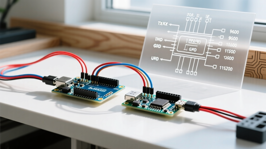
Yes, absolutely. UART is a single-ended protocol that requires a common voltage reference. If you only connect the TX and RX lines without connecting the Ground (GND) pins, the receiver has no baseline to measure the 5V or 3.3V logic high/low states against. The floating ground will cause random noise to be interpreted as serial data. Always run a dedicated GND wire alongside your TX/RX pair. The only exception is if you are using optical isolators (like the HCPL-2630) or digital isolators (like the ISO7721) to intentionally break a ground loop in high-voltage industrial environments.
Troubleshooting Matrix
| Symptom | Probable Cause | Actionable Fix |
|---|---|---|
| Receiver gets nothing (Silent) | TX/RX swapped or missing GND | Swap TX and RX wires. Verify GND is connected between both boards. |
| Garbage characters (e.g., ÿ, ?) | Baud rate mismatch or clock drift | Verify Serial.begin() matches exactly. Drop to 9600 or 57600 to test for clock drift. |
| Intermittent data loss | Buffer overflow on receiver | Receiver isn't reading fast enough. Increase receiver's serial buffer size or use hardware flow control (RTS/CTS). |
| Works on desk, fails in enclosure | EMI / Ground Loop noise | Switch to twisted pair wiring. Add 0.1µF decoupling capacitors near MCU VCC pins. Consider RS-485. |
| ESP32 reboots randomly | 5V logic injected into 3.3V RX pin | Immediately disconnect! Install a BSS138 or TXS0108E logic level shifter on the RX line. |
Final Thoughts on Multi-MCU Architectures
As projects scale in 2026, treating serial communication as an afterthought will lead to endless debugging sessions. By respecting logic level thresholds, calculating baud rate errors based on your specific crystal oscillators, and implementing binary framing with checksums, your Arduino to Arduino communication serial links will be as robust as industrial PLC networks. Always prototype your data framing on a single MCU using software serial or loopback testing before deploying it across multiple physical boards.
Authoritative Sources
- Arduino Official Serial Reference Documentation - Comprehensive guide to hardware serial buffers and baud rate configurations.
- SparkFun Engineering: Logic Levels Tutorial - Essential reading on 3.3V vs 5V logic thresholds and safe translation methods.
- Texas Instruments RS-485 Overview & Design Guides - Industry standards for long-distance differential serial communication.