
The "Hello World" of Microcontrollers
Figuring out how to blink a LED Arduino style is the foundational rite of passage for every embedded systems engineer and hobbyist. While it seems trivial, this single exercise validates your toolchain, verifies your board's bootloader, and confirms your understanding of basic digital I/O (Input/Output) and current-limiting circuits. In 2026, with the widespread adoption of the Arduino Uno R4 Minima and the legacy Uno R3 still holding strong in educational labs, the core principles remain identical, though the underlying silicon and IDE environments have evolved.
This quick reference guide bypasses the fluff and delivers exact wiring matrices, Ohm's law calculations for current limiting, and advanced troubleshooting edge cases for modern Arduino IDE 2.x environments.
Quick Reference Bill of Materials (BOM)
Before wiring, ensure you have the correct components. Using an LED without a current-limiting resistor is the most common beginner mistake, leading to immediate component failure or damaged microcontroller I/O pins.
| Component | Specification | 2026 Avg. Cost | Technical Notes |
|---|---|---|---|
| Microcontroller | Arduino Uno R4 Minima | $19.50 | Features a 32-bit ARM Cortex-M4 (RA4M1). I/O pins are 5V tolerant. |
| LED | 5mm Diffused Red | $0.10 | Typical Forward Voltage (Vf): 2.0V. Max Continuous Current: 20mA. |
| Resistor | 220Ω 1/4W Carbon Film | $0.02 | Limits current to a safe ~13.6mA on a 5V logic pin. |
| Jumper Wires | M-M Dupont 22AWG | $3.50 / 120-pack | Standard male-to-male for breadboard prototyping. |
Pinout & Wiring Matrix
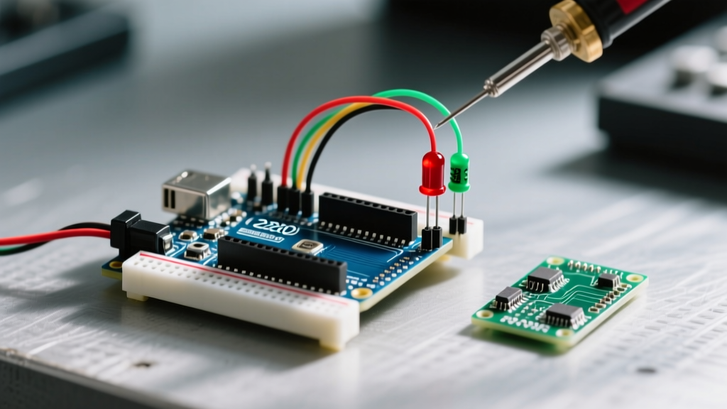
When wiring an external LED, you must respect polarity. LEDs are diodes; they only allow current to flow in one direction.
- Anode (Long Leg / Positive): Connects to the current-limiting resistor, which then routes to Digital Pin 13 (or any configured digital I/O pin).
- Cathode (Short Leg / Flat Edge / Negative): Connects directly to the GND (Ground) rail on the Arduino.
Pro-Tip: If you are using a surface-mount device (SMD) LED or a 5mm LED with trimmed legs, look for the flat notch on the plastic base of the LED. The side with the flat edge is always the Cathode (Ground).
The Code: Blocking vs. Non-Blocking
The standard "Blink" sketch uses the delay() function. While fine for testing, delay() halts the microcontroller's CPU, preventing it from reading sensors or handling serial communication simultaneously.
1. The Standard Blocking Sketch (Quick Test)
void setup() {
  pinMode(13, OUTPUT); // Initialize digital pin 13 as an output
}

void loop() {
  digitalWrite(13, HIGH); // Turn the LED on (HIGH voltage level)
  delay(1000);            // Wait for 1000 milliseconds (1 second)
  digitalWrite(13, LOW);  // Turn the LED off (LOW voltage level)
  delay(1000);            // Wait for a second
}
2. The Non-Blocking Sketch (Production Ready)
For real-world applications, use the millis() timer to track time without pausing the CPU.
const int ledPin = 13;
int ledState = LOW;
unsigned long previousMillis = 0;
const long interval = 1000;

void setup() {
  pinMode(ledPin, OUTPUT);
}

void loop() {
  unsigned long currentMillis = millis();
  if (currentMillis - previousMillis >= interval) {
    previousMillis = currentMillis;
    ledState = (ledState == LOW) ? HIGH : LOW;
    digitalWrite(ledPin, ledState);
  }
  // CPU is free to execute other tasks here
}
Frequently Asked Questions (FAQ)
Why do I need a resistor, and how do I calculate the exact value?
Microcontroller I/O pins attempt to maintain a set voltage (e.g., 5V). An LED has very little internal resistance once its forward voltage threshold is met. Without a resistor, the LED will draw maximum current from the pin, instantly burning out the LED or frying the microcontroller's internal trace. We use Ohm's Law to calculate the required resistance:
Formula: R = (V_source - V_forward) / I_desired
- V_source: 5V (Arduino Uno logic HIGH)
- V_forward: 2.0V (Standard Red LED)
- I_desired: 0.015A (15mA - a safe, bright operating current)
R = (5 - 2.0) / 0.015 = 200Ω. Since 200Ω is not a standard E12 resistor value, we round up to the nearest standard value: 220Ω.
Can I just use the onboard LED instead of wiring an external one?
Yes. Almost all Arduino boards feature a built-in LED tied to Pin 13. In modern Arduino IDE versions, it is best practice to use the LED_BUILTIN macro rather than hardcoding 13. This ensures your code remains portable across different architectures, such as the Arduino Nano ESP32 or the MKR WiFi 1010, where the onboard LED might be mapped to a different physical pin.
What happens if I use a Blue or White LED with a 220Ω resistor?
Blue, Green, and White LEDs typically have a higher forward voltage (Vf ≈ 3.0V to 3.3V). If you use a 220Ω resistor on a 5V pin with a Blue LED (Vf = 3.2V), the current drops to (5 - 3.2) / 220 = 8.1mA. The LED will illuminate, but it will appear noticeably dim. For high-Vf LEDs on 5V logic, drop down to a 100Ω resistor to achieve optimal brightness without exceeding the 20mA pin limit.
Are Arduino Uno R4 pins 5V or 3.3V?
The Uno R4 Minima and WiFi utilize the Renesas RA4M1 processor, which natively operates at 3.3V logic. However, Arduino engineered the board with level-shifting circuitry to make the digital I/O pins 5V tolerant. This means you can still safely drive a standard 5V LED circuit and interface with legacy 5V sensors without frying the ARM Cortex-M4 chip.
Advanced Troubleshooting Edge Cases
When your circuit fails to illuminate, work through this systematic diagnostic checklist before assuming hardware failure.
- Reversed Polarity: The most common physical error. Swap the anode and cathode connections. Unlike incandescent bulbs, LEDs will not be damaged by being inserted backward; they simply block current flow.
- IDE 2.x Port Selection: Unlike the legacy 1.8.x IDE, Arduino IDE 2.3+ does not always auto-prompt for port selection when a new board is connected. Click the drop-down menu in the top-left toolbar and manually verify that the correct COM port (Windows) or /dev/cu.usbmodem (macOS) is selected.
- The "Dim Glow" Phenomenon: If your external LED glows faintly even when the pin is set to
LOW, you may be experiencing phantom voltage or floating pin states. Ensure your ground wire is securely seated in the breadboard's ground rail and that you are not accidentally using a PWM pin with a lingering capacitor charge. - Exceeding Absolute Maximum Ratings: According to the Arduino Official Documentation, the absolute maximum DC current per I/O pin is 40mA, but the recommended continuous operating current is 20mA. Furthermore, the total current sourced from all VCC/GND pins combined must not exceed 200mA. If you plan to blink multiple LEDs simultaneously, you must use a logic-level MOSFET (like the IRLZ44N) or a BJT transistor (like the 2N2222) to switch the load directly from the 5V rail.
Further Reading & Authoritative Resources
To deepen your understanding of component physics and embedded programming, consult these foundational resources:
- SparkFun: Light Emitting Diodes (LEDs) Tutorial - An exhaustive breakdown of LED physics, forward voltage bins, and thermal management.
- Arduino Official Blink Documentation - The canonical reference for the Blink sketch, including hardware-specific variations for the entire Arduino ecosystem.