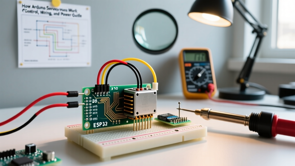

There are few things more frustrating in embedded systems development than uploading a sketch, opening the Serial Monitor, and watching your digital input stubbornly report a HIGH state regardless of what you do with the physical button or sensor. The 'Arduino read always high' dilemma is one of the most frequently debated topics on maker forums, StackExchange, and Discord communities. Whether you are using a classic Arduino Uno R3, a Nano Every, or an ESP32 dev board, a pin stuck at logic level 1 usually points to one of three culprits: floating CMOS inputs, logic-level mismatches, or catastrophic GPIO damage.
In this community resource roundup, we have synthesized the most effective, field-tested troubleshooting frameworks from expert electrical engineers and veteran makers. We will bypass the generic 'check your wiring' advice and dive deep into silicon-level diagnostics, exact multimeter testing procedures, and hardware modifications to permanently solve your stuck-high pin issues.
The Community Diagnostic Matrix: Why is Your Pin Stuck HIGH?
Before desoldering components or rewriting your sketch, use this diagnostic matrix compiled from hundreds of forum threads to isolate your exact failure mode.
| Symptom / Behavior | Multimeter Reading (Pin to GND) | Probable Root Cause | Community-Backed Fix |
|---|---|---|---|
| Reads HIGH when unconnected, random flickering | 0.2V - 2.5V (Fluctuating) | Floating CMOS Input (Antenna Effect) | Enable INPUT_PULLUP or add 10kΩ external pull-down |
| Reads HIGH even when jumpered directly to GND | ~0.4V - 0.6V | Internal ESD protection diode shorted to VCC | Replace ATmega328P-PU IC or switch to a new GPIO pin |
| Reads HIGH only when a motor/relay activates | Spikes to 3V+ momentarily | EMI / Inductive Kickback / Ground Bounce | Add 100nF ceramic bypass cap and 1N4007 flyback diode |
| Reads HIGH constantly with 3.3V sensor on 5V board | Steady 3.3V | Logic threshold mismatch / Sensor output limit | Use BSS138 Logic Level Converter or adjust code thresholds |
1. The 'Floating Pin' Phenomenon and CMOS Impedance
The most common cause of an erratic or permanently high reading is a floating pin. Microcontroller GPIO pins (including the ATmega328P and ESP32) utilize CMOS (Complementary Metal-Oxide-Semiconductor) technology. CMOS inputs have extraordinarily high impedance—often in the range of 100 MΩ or more. When a pin is not actively driven HIGH or LOW by a circuit, it acts like an antenna, picking up ambient electromagnetic interference (EMI) from nearby AC mains, switching power supplies, or even your own body's capacitance.
The Pull-Up vs. Pull-Down Debate
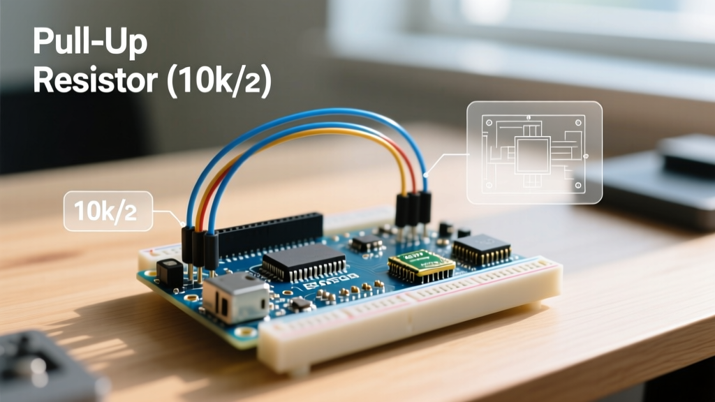
According to the SparkFun Pull-Up Resistor Tutorial, leaving an input unconnected is a cardinal sin in circuit design. To fix a floating pin that defaults to HIGH due to noise, you must provide a defined DC path to either VCC or GND.
- External Pull-Down (10kΩ): If your sensor outputs a HIGH signal when triggered (Active-High), wire a 10kΩ resistor between the digital pin and GND. This ensures the pin reads a solid LOW when the sensor is off, overcoming ambient noise without drawing excessive current (only 0.5mA at 5V).
- Internal Pull-Up (
INPUT_PULLUP): The ATmega328P features internal pull-up resistors typically ranging from 20kΩ to 50kΩ. You can enable these in your sketch usingpinMode(pin, INPUT_PULLUP);. Note: This inverts your logic. A pressed button (connected to GND) will read LOW, while an open button will read HIGH.
2. The 'Fried GPIO' Test: Multimeter Diode Diagnostics
If your code is correct, your pull-down resistors are soldered properly, and the pin still reads HIGH—even when you physically short the pin to the Arduino's GND header with a jumper wire—your GPIO pin is likely dead. This happens when a voltage exceeding VCC + 0.5V is fed into the pin, destroying the internal silicon ESD protection diodes and permanently shorting the pin to the VCC rail.
Step-by-Step Silicon Health Check
Veteran forum members recommend the following diode-test procedure to confirm hardware damage without needing an oscilloscope:
- Power OFF the Arduino completely and disconnect USB.
- Set your digital multimeter (e.g., Fluke 117 or ANENG AN8008) to Diode Test Mode.
- Place the Red probe on the Arduino GND pin.
- Place the Black probe on the suspect digital pin (e.g., D2).
Interpreting the Results:
- 0.5V to 0.7V: The pin is healthy. You are reading the forward voltage drop of the intact protection diode.
- 0.00V (Short): The internal diode has failed short. The pin is permanently tied to VCC internally. This is the definitive cause of your 'Arduino read always high' hardware fault.
- OL (Open Loop): The internal bond wire connecting the silicon die to the package pin has vaporized due to overcurrent.
Repair Note: If you are using a through-hole Arduino Uno or Nano clone with a socketed DIP-28 ATmega328P-PU chip, you can simply buy a replacement microcontroller for roughly $2.85 (2026 Mouser/DigiKey pricing) and swap it out. If you are using an ESP32 or a surface-mount Nano, you must abandon the fried pin and reassign your wiring to an unused GPIO.
3. Logic Level Mismatches and Sensor Latch-Up
Another frequent culprit identified in the Arduino Digital Pins Foundation Guide involves mixing 5V and 3.3V logic ecosystems. A classic example is wiring a 5V HC-SR501 PIR motion sensor or an HC-SR04 Ultrasonic sensor's Echo pin directly to a 3.3V microcontroller like the ESP32 or Arduino Due.
While some ESP32 pins claim 5V tolerance in specific input modes, continuous exposure to 5V on a 3.3V CMOS gate can cause latch-up. Latch-up is a state where a parasitic thyristor structure inside the silicon turns on, creating a low-impedance path between VCC and GND. This not only causes the pin to read a permanent HIGH but can also overheat the microcontroller and destroy the USB voltage regulator. Always use a bidirectional logic level converter (like the Texas Instruments TXS0108E or a simple BSS138 MOSFET breakout board costing ~$3.50) when bridging 5V sensors to 3.3V MCUs.
4. Ground Bounce and Inductive Kickback
If your Arduino reads HIGH only intermittently—specifically when a relay clicks, a solenoid fires, or a DC motor spins—you are experiencing ground bounce or EMI. High-current inductive loads share a ground return path with the Arduino's low-voltage logic. When the inductive load switches off, the collapsing magnetic field generates a massive voltage spike (inductive kickback) that can momentarily lift the Arduino's local ground reference by several volts. To the microcontroller's internal comparator, this ground shift looks exactly like a HIGH signal on the input pin.
The Hardware Fix
'Never share a ground wire between a high-current motor driver and a sensitive digital sensor. Run a star-ground topology back to the main power supply, and place a 100nF X7R ceramic capacitor directly across the sensor's VCC and GND pins at the connector.' — Embedded Systems Engineering Forum Consensus
Additionally, ensure all relays and motors are equipped with flyback diodes (e.g., 1N4007) wired in reverse-bias across the inductive coil to safely dissipate the kickback energy.
Essential 2026 Troubleshooting Toolkit
To move beyond guesswork, community experts recommend keeping the following diagnostic tools at your maker bench:
- Saleae Logic Pro 8 ($599) or DSLogic Plus ($199): A logic analyzer will instantly show you if a pin is truly HIGH, or if it is oscillating at 50kHz due to noise, which a multimeter will average out and display as a false 'HIGH' voltage.
- True-RMS Multimeter: Essential for the diode-test and continuity checks mentioned above.
- BSS138 Logic Level Shifters: Keep a few of these $2 breakout boards in your bin to eliminate 5V/3.3V mismatch issues permanently.
Summary
When your Arduino digital input refuses to drop LOW, resist the urge to immediately rewrite your software. The 'Arduino read always high' issue is overwhelmingly a hardware or wiring fault. By systematically checking for floating CMOS inputs, verifying logic-level compatibility, and performing a multimeter diode test to rule out fried silicon, you can isolate the fault in minutes. Implement proper pull-down resistors, respect the absolute maximum voltage ratings of your microcontroller, and use star-grounding techniques to ensure your digital reads remain clean, stable, and accurate.