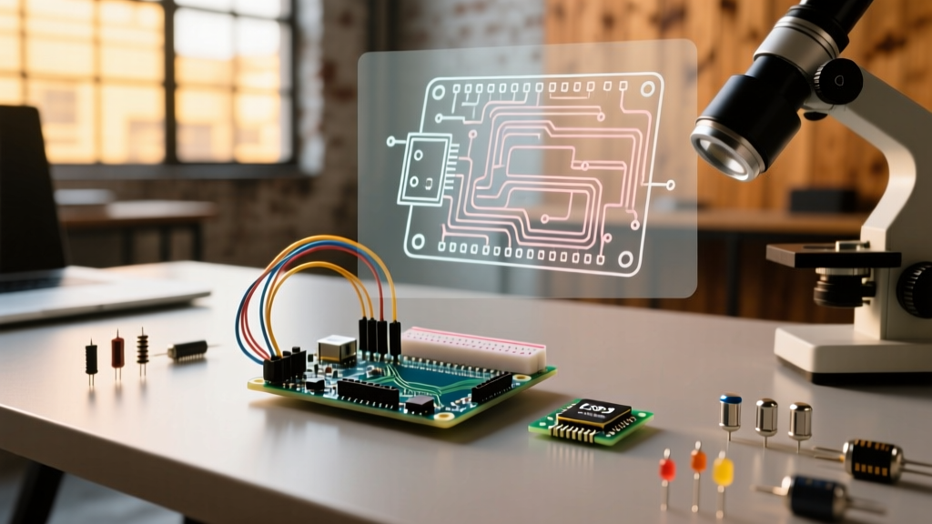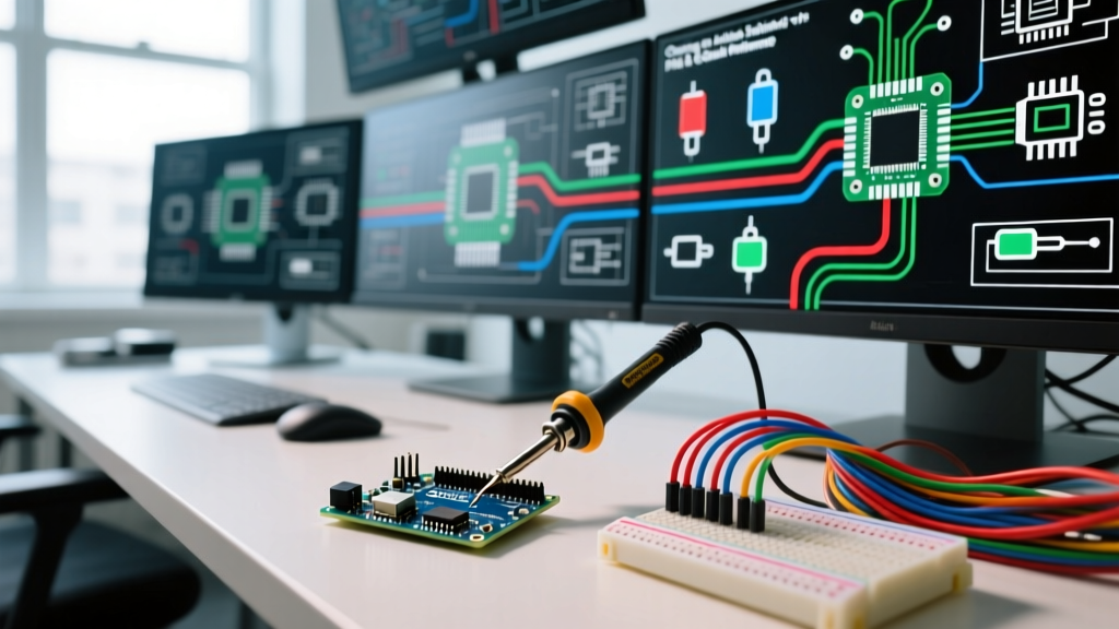

The Ultimate Arduino Schematic Creator FAQ & Quick Reference
Transitioning from a tangled breadboard prototype to a manufactured Printed Circuit Board (PCB) is a major milestone for any electronics maker. However, selecting the right Arduino schematic creator can be overwhelming given the sheer number of Electronic Design Automation (EDA) tools available in 2026. Whether you are designing a simple Arduino Uno R4 shield or a complex custom board featuring an ESP32-S3 and a BME280 sensor, your choice of software dictates your workflow, component availability, and manufacturing success.
This comprehensive FAQ and quick reference guide cuts through the marketing fluff. We provide actionable, deeply technical answers to the most common questions makers and engineers ask when choosing and using schematic capture tools for microcontroller projects.
Quick Comparison Matrix: Top Schematic Tools for MCU Design
Before diving into specific troubleshooting and workflow questions, review this high-level comparison of the most popular schematic creators used in the Arduino and maker community.
| Tool | Cost (2026) | Learning Curve | PCB Export / Gerber | Best Use Case |
|---|---|---|---|---|
| KiCad (v8/v9) | Free (Open Source) | Moderate to Steep | Full Gerber / ODB++ | Professional-grade custom MCU boards, complex shields. |
| EasyEDA (Standard/Pro) | Free / $9.9/mo | Low to Moderate | Full Gerber / Pick & Place | Rapid prototyping, direct JLCPCB/LCSC integration. |
| Fritzing | ~$8 (Binary download) | Very Low | Basic Gerber (Limited) | Visual documentation, educational wiring diagrams. |
| Tinkercad Circuits | Free (Web-based) | Very Low | None | Beginner logic simulation, basic Arduino wiring visualization. |
| Altium Designer | ~$10,000+ | Very Steep | Full Manufacturing Suite | Enterprise-level, high-speed multi-layer MCU designs. |
Frequently Asked Questions (FAQ)
1. What is the best free Arduino schematic creator for beginners?
If your goal is to eventually manufacture a physical PCB, EasyEDA (Standard) is the best starting point for beginners in 2026. Its web-based interface eliminates installation headaches, and it features a massive, community-contributed component library. When you need an ATmega328P-AU microcontroller or a specific 0805 decoupling capacitor, you can search the integrated LCSC library and drop the exact footprint directly into your schematic.
However, if your goal is purely to document a breadboard circuit for a blog post or school project without manufacturing intent, Fritzing remains the king of visual, pseudo-schematic breadboard layouts. Just be aware that Fritzing's actual schematic capture and PCB routing environments are notoriously clunky compared to modern EDA suites.
2. Can I use Fritzing for professional PCB manufacturing?
While Fritzing does export Gerber files, it is highly discouraged for professional or complex manufacturing. Fritzing struggles with Design Rule Checks (DRC), meaning it will not warn you if your 5V trace is too close to a ground pad, potentially resulting in short circuits when fabricated. Furthermore, creating custom footprints for newer components (like the Qwiic/STEMMA QT connectors or modern BGA packages) in Fritzing is an exercise in frustration. For any board going to a fab house like PCBWay or JLCPCB, migrate to KiCad or EasyEDA.
3. How do I manage custom Arduino board footprints in KiCad?
KiCad is the undisputed champion of open-source EDA tools, but its library management can confuse newcomers. To design a shield for an official board, you need the exact mechanical dimensions. According to the official Arduino hardware documentation, the standard Arduino Uno mounting holes and header spacing are strictly defined.
Step-by-Step Footprint Import:
- Download the official KiCad library for Arduino shields from the KiCad community repositories or third-party sites like SnapEDA.
- Open the KiCad Footprint Editor and import the
.kicad_modfile. - Verify the pad spacing. Standard Arduino headers use a 2.54mm (0.1 inch) pitch. The distance between the two 8-pin and 6-pin headers on an Uno is exactly 48.26mm.
- Assign this footprint to your schematic symbol using the 'Footprint' field in the symbol properties.
4. Why does my schematic fail the Design Rule Check (DRC) during PCB layout?
DRC failures are the most common roadblock when moving from schematic capture to PCB routing. The schematic itself rarely fails DRC; rather, the netlist generated from the schematic creates physical violations during layout. Common edge cases include:
- Trace Clearance Violations: Standard 2-layer PCB fab houses require a minimum 6mil (0.15mm) clearance between copper features. If your schematic assigns a 10mil net class to your I2C lines but you route them too close to a ground pour, the DRC will flag it.
- Annular Ring Size: Vias must have sufficient copper around the drilled hole. A standard via is 0.3mm drill with a 0.6mm pad. If your schematic netclass dictates a 0.4mm pad for a 0.3mm drill, the fab house may reject the Gerber files due to drill breakout risks.
- Unconnected Pins: Forgetting to tie the
RESETpin to VCC via a 10k pull-up resistor, or leaving theAVCCpin floating on an ATmega328P, will trigger Electrical Rules Check (ERC) warnings in the schematic phase.
5. Is Altium Designer overkill for standard Arduino clones?
Yes. Altium Designer is an enterprise-grade tool utilized for 12-layer motherboards with controlled impedance DDR4 memory routing. Using Altium for a 2-layer Arduino Nano clone is like using a CNC 5-axis mill to cut a piece of balsa wood. The licensing costs upwards of $10,000, and the interface is optimized for high-speed signal integrity analysis, not quick maker prototyping. Stick to KiCad for 95% of MCU projects.
Quick Reference: Pre-Export Gerber Checklist
Before you send your design files to a manufacturer, run through this critical checklist to ensure your schematic translates perfectly to physical copper. For a deeper understanding of manufacturing file standards, refer to the Gerber format documentation.
Pro-Tip: Always order a 'stencil' if your custom Arduino board uses surface-mount components smaller than 0805 or features QFP/QFN microcontroller packages. Hand-soldering an ESP32-WROOM module with a standard iron is a recipe for bridged pads.
- ERC (Electrical Rules Check): Run this in the schematic editor. Zero errors allowed. Warnings for unpowered pins should be manually verified and flagged with PWR_FLAG symbols.
- Decoupling Capacitors: Ensure every VCC pin on your MCU has a 100nF (0.1µF) ceramic capacitor placed as close to the pin as physically possible in the layout.
- I2C Pull-ups: Verify 4.7kΩ pull-up resistors are present on SDA and SCL lines if your peripheral sensors do not have them onboard.
- Silkscreen Text: Check that silkscreen text is at least 1.0mm high and 0.15mm line width so it remains legible after manufacturing.
- Mounting Holes: Confirm mounting holes are unplated and properly grounded if they are meant to serve as mechanical standoffs rather than electrical connections.
Final Thoughts on MCU Schematic Capture
The ideal Arduino schematic creator depends entirely on your end goal. For rapid, web-based iteration with seamless parts sourcing, EasyEDA is unmatched. For rigorous, offline, professional-grade open-source design, KiCad is the industry standard. By understanding the specific design rules, footprint requirements, and DRC parameters outlined in this guide, you will eliminate the most common manufacturing errors and transition from breadboard to bespoke PCB with confidence.