
The Anatomy of an Interrupt Failure
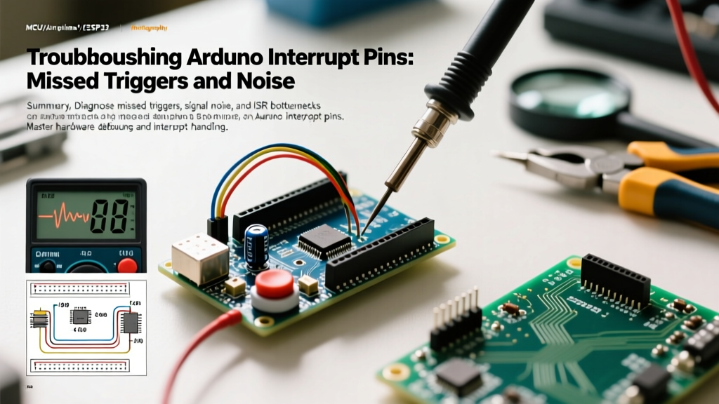
When building precision timing circuits, tachometers, or high-speed encoders, relying on digitalRead() inside the main loop() is a recipe for missed data. Hardware interrupts bypass the main loop, forcing the microcontroller to immediately execute an Interrupt Service Routine (ISR). However, when your encoder skips steps or your tachometer registers phantom RPMs, the issue rarely lies in the concept of interrupts itself. The failure almost always stems from misconfigured Arduino interrupt pins, electrical noise, or ISR execution bottlenecks.
In 2026, the maker ecosystem spans from legacy 8-bit ATmega328P boards to dual-core ESP32-S3 microcontrollers. Diagnosing interrupt failures requires a bifurcated approach: understanding the physical silicon limitations of your specific MCU and auditing your signal integrity. Below is a comprehensive diagnostic framework for resolving the most common interrupt anomalies.
Hardware Pin Mapping: The Most Common Culprit
The most frequent cause of a 'dead' interrupt is attempting to attach an ISR to a GPIO pin that does not support external hardware interrupts on your specific microcontroller. While the Arduino IDE abstracts much of the hardware, attachInterrupt(digitalPinToInterrupt(pin), ISR, mode) will silently fail if the pin lacks an external interrupt vector (INTx).
MCU Interrupt Pin Matrix
| Microcontroller | Common Board Models | Valid External Interrupt Pins | Architectural Notes |
|---|---|---|---|
| ATmega328P | Uno R3, Nano, Pro Mini | D2 (INT0), D3 (INT1) | Strict hardware mapping. Only 2 pins available. |
| ATmega2560 | Mega 2560 | D2, D3, D18, D19, D20, D21 | 6 dedicated INTx vectors. |
| ESP32 / ESP32-S3 | NodeMCU-32S, ESP32-S3-DevKitC | Almost all GPIOs (via GPIO Matrix) | Avoid strapping pins (GPIO 0, 3, 12) and SPI flash pins (6-11). |
| RP2040 | Raspberry Pi Pico | All GPIOs (0-29) | Highly flexible, routed via IO bank IRQs. |
Diagnostic Tip: If you are using an ATmega328P and run out of D2 and D3, you must pivot to Pin Change Interrupts (PCINT). Libraries like EnableInterrupt allow any digital pin to trigger an ISR, though they require manual port-register parsing to determine exactly which pin changed state.
Signal Integrity: Bounce, Noise, and Phantom Triggers
If your interrupt is mapping correctly but triggering erratically, you are likely a victim of switch bounce or Electromagnetic Interference (EMI). Mechanical switches and relays physically 'bounce' for 1 to 15 milliseconds upon actuation. To a 16MHz AVR or 240MHz ESP32, a single button press looks like 50 rapid-fire interrupts.
Hardware vs. Software Debouncing
While software debouncing (ignoring triggers within a 50ms window using millis()) is common, it introduces latency and wastes CPU cycles checking timestamps inside the ISR. For high-speed applications like optical encoders spinning at 3,000 RPM, software debouncing will cause missed pulses.
The Hardware Solution: Implement a low-pass RC filter combined with a Schmitt trigger.
- Stage 1 (RC Filter): Place a 10kΩ series resistor and a 100nF ceramic capacitor to ground. This yields a time constant ($\tau$) of 1ms, effectively smoothing out microsecond-level contact bounce.
- Stage 2 (Schmitt Trigger): Route the filtered signal through a 74HC14N hex inverter (costing roughly $0.40 per IC). The Schmitt trigger's hysteresis ensures a crisp, clean digital edge, completely eliminating the slow voltage ramp that can cause the MCU's internal comparator to oscillate.
For environments with heavy EMI (e.g., CNC routers, stepper motor drivers like the DRV8825, or high-current relays), use shielded twisted-pair cables for your interrupt signals and terminate them with a 10kΩ pull-up resistor directly at the microcontroller pin to lower the impedance and increase noise immunity.
ISR Execution Time: The Silent Loop Killer
An ISR pauses the main program, suspends other interrupts, and halts background timing functions (like millis() and delay()). If your ISR takes too long to execute, you will experience system-wide lockups or missed subsequent triggers.
Golden Rule of ISRs: Never use
delay(), never useSerial.print(), and avoid floating-point math inside an interrupt. According to SparkFun's comprehensive guide on microcontroller interrupts, an ISR should only set a flag or increment a counter, deferring heavy processing to the main loop.
Code Architecture: The Flag Pattern
Instead of processing data inside the ISR, use a volatile boolean flag to signal the main loop.
// Inside ISR
volatile bool pulseDetected = false;
void countPulse() {
pulseCount++;
pulseDetected = true;
}
// Inside main loop()
if (pulseDetected) {
pulseDetected = false;
// Perform heavy calculations, Serial prints, or LCD updates here
}
Variable Corruption and the 'Volatile' Trap
A deeply insidious bug occurs when a variable modified by an ISR is read in the main loop without proper atomic protection or the volatile keyword. The C++ compiler aggressively optimizes code. If it sees a variable in the main loop that isn't explicitly modified within that loop's scope, it may cache the variable in a CPU register, completely ignoring the updates happening in the ISR.
Always declare ISR-shared variables as volatile. For example: volatile unsigned long encoderTicks = 0;.
Atomic Operations on 8-bit AVRs
On 8-bit microcontrollers like the ATmega328P, reading a 32-bit long or unsigned long requires four separate clock cycles. If an interrupt fires between the second and third byte read, the main loop will assemble a 'frankenstein' value—half from the old state, half from the new state—resulting in massive, erratic data spikes.
To prevent this, you must disable interrupts momentarily while reading multi-byte variables using the util/atomic.h library:
#include <util/atomic.h>
unsigned long localCopy;
ATOMIC_BLOCK(ATOMIC_RESTORESTATE) {
localCopy = encoderTicks;
}
This ensures the read operation is uninterrupted, a critical technique detailed in Arduino's official attachInterrupt() documentation.
Step-by-Step Diagnostic Flowchart
When your interrupt-driven sketch fails, follow this sequential diagnostic path:
- Verify Pin Capability: Confirm your chosen GPIO supports hardware interrupts on your specific MCU (refer to the matrix above).
- Check Trigger Mode: Are you using
LOWas the trigger mode?LOWwill repeatedly fire the ISR as long as the pin is grounded, starving the main loop. Switch toFALLINGorRISING. - Scope the Signal: Connect a logic analyzer or oscilloscope. Look for slow rise times (needs a pull-up resistor or Schmitt trigger) or high-frequency noise (needs an RC filter).
- Audit the ISR Payload: Ensure no
SerialorWire(I2C) functions are executing inside the ISR. I2C relies on its own interrupts; calling it inside an ISR causes a deadlock. - Verify Atomic Reads: Ensure all multi-byte variables shared with the main loop are wrapped in an
ATOMIC_BLOCKor protected bycli()/sei().
Advanced Edge Cases: ESP32 GPIO Matrix Conflicts
If you have migrated to the ESP32 ecosystem for its superior processing power, be aware of the GPIO matrix. While Espressif's interrupt allocation API allows almost any pin to act as an interrupt, routing signals through the matrix adds a slight propagation delay (roughly 25-50 nanoseconds). For 99% of maker applications, this is negligible. However, if you are building high-frequency RF counters or sub-microsecond pulse width measurement tools, you must use the dedicated, direct-pad pins to bypass the matrix latency.
Furthermore, never attach interrupts to ESP32 strapping pins (like GPIO 0, 2, or 12) if the external circuit might pull them low or high during the bootloader sequence, as this will brick the boot process or cause immediate panic resets.
Conclusion
Mastering Arduino interrupt pins requires looking beyond the IDE's simplified syntax. By matching the correct hardware pin to your MCU's architecture, conditioning your signals with proper RC and Schmitt trigger networks, and enforcing strict atomic variable handling, you can eliminate missed triggers and build robust, industrial-grade sensor interfaces.