
Quick Reference: Building a Precision Arduino RPM Gauge
Designing an Arduino RPM gauge requires more than just taping a magnet to a shaft and calling a function. Whether you are building a tachometer for a brushed DC motor, a CNC spindle, or a small engine, accuracy hinges on sensor selection, hardware debouncing, and non-blocking interrupt service routines (ISRs). This quick-reference FAQ addresses the most common engineering hurdles, edge cases, and calibration techniques encountered by makers and embedded engineers in 2026.
Sensor Selection Matrix
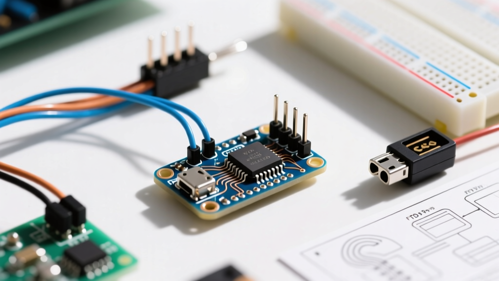
Choosing the right transducer is the first critical step. Below is a comparison of the three most common sensor modules used in DIY and prototyping tachometers.
| Sensor Model | Type | Max Frequency | Avg. Cost (2026) | Best Application |
|---|---|---|---|---|
| A3144 | Hall Effect (Unipolar) | ~10 kHz | $0.15 / ea | High-vibration, dirty environments, ferrous targets |
| TCRT5000 | IR Reflective | ~5 kHz | $0.80 / ea | Low-RPM optical targets, clean environments, reflective tape |
| H21L1 / FC-33 | Optical Slotted Encoder | ~20 kHz | $1.20 / ea | High-RPM shaft encoding, precise edge detection, CNC spindles |
Frequently Asked Questions (FAQ)
1. Why is my Hall Effect sensor output bouncing or giving double readings?
The A3144 Hall Effect sensor features an open-collector output. If you rely solely on the microcontroller's internal pull-up resistor (INPUT_PULLUP), the high-impedance state can act as an antenna, picking up electromagnetic interference (EMI) from nearby motors or ignition coils. This results in 'bouncing'—where a single magnet pass triggers multiple interrupts.
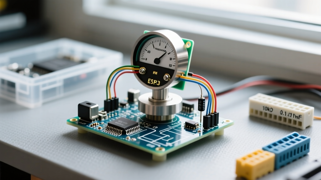
The Fix: Use an external 10kΩ pull-up resistor connected directly to the 5V rail at the sensor's physical location, not at the Arduino end. Additionally, solder a 100nF (0.1µF) ceramic decoupling capacitor across the VCC and GND pins of the sensor to filter out high-frequency brush noise from DC motors.
2. Should I use polling or hardware interrupts for RPM measurement?
Never use polling (digitalRead() in the main loop) for an Arduino RPM gauge if the target exceeds 1,000 RPM. The main loop execution time varies, especially if you are updating an I2C OLED display or writing to an SD card. You will inevitably miss pulses.
Instead, use hardware interrupts via the Arduino attachInterrupt() Reference. On an ATmega328P (Uno/Nano), pins 2 and 3 are tied to INT0 and INT1. Configure the interrupt to trigger on the FALLING edge to ensure you only capture one transition per magnet pass.
3. What is the exact mathematical formula for calculating RPM?
RPM is derived from the time elapsed between consecutive pulses. Because microcontrollers operate in microseconds, the standard formula is:
RPM = 60,000,000 / (Delta_Microseconds * Pulses_Per_Revolution)
Where Delta_Microseconds is the difference between the current micros() timestamp and the previous timestamp. If your shaft has 4 magnets spaced evenly, your Pulses Per Revolution (PPR) is 4. Always verify your PPR physically with an oscilloscope or logic analyzer before hardcoding it into your sketch.
4. How do I prevent division-by-zero errors when the motor stalls?
A common failure mode in DIY tachometers occurs when the motor stops. The time between pulses approaches infinity, and if your code attempts to calculate RPM before a new pulse arrives, it may divide by zero or display a frozen, outdated value.
The Fix: Implement a timeout threshold in your main loop. If micros() - lastPulseTime exceeds a specific threshold (e.g., 500,000 µs, which equates to 120 RPM for a 1-PPR setup), force the RPM variable to zero.
5. Why does my I2C display freeze at high RPMs?
Updating an I2C display (like the ubiquitous SSD1306 OLED or PCF8574-backed 16x2 LCD) takes between 3ms and 15ms. If you attempt to update the display inside the ISR, or if you update it on every single pulse in the main loop, the I2C bus will bottleneck. At high RPMs, the microcontroller spends 100% of its time updating the screen and stops processing incoming interrupts.
Best Practice: Keep your ISR strictly limited to timestamping. Use a non-blocking millis() timer in the main loop to update the display exactly 4 times per second (every 250ms). This provides a smooth visual update rate without starving the CPU.
Troubleshooting Matrix: Common RPM Gauge Failures
| Symptom | Root Cause | Engineering Fix |
|---|---|---|
| RPM reads exactly double the actual speed | Interrupt configured to CHANGE instead of FALLING |
Change ISR mode to FALLING to trigger only on the high-to-low transition. |
| Erratic spikes at high speeds | EMI from brushed motor commutator arcing | Route sensor signal through a twisted-pair shielded cable; add an RC low-pass filter (1kΩ + 1nF). |
| Gauge reads 0 RPM intermittently | Race condition when reading 32-bit micros() variable |
Disable interrupts (noInterrupts()), copy the volatile timestamp to a local variable, and re-enable (interrupts()) before doing math. |
| Sensor fails to trigger above 5,000 RPM | Magnet passing too quickly for sensor hysteresis | Switch from A3144 (Hall) to an H21L1 (Optical Slotted) sensor with faster nanosecond response times. |
Advanced ISR Implementation Strategy
For those writing production-grade firmware for an Arduino RPM gauge, understanding atomic operations is vital. The micros() function returns a 32-bit unsigned long. On an 8-bit AVR microcontroller, reading a 32-bit variable takes multiple clock cycles. If an interrupt fires while the main loop is reading this variable, the data will be corrupted (torn read).
As detailed in the excellent SparkFun Introduction to Interrupts, you must protect shared volatile variables:
volatile unsigned long lastPulseTime = 0;
volatile unsigned long pulseInterval = 0;

void isrPulse() {
  unsigned long now = micros();
  pulseInterval = now - lastPulseTime;
  lastPulseTime = now;
}

void loop() {
  unsigned long safeInterval;
  noInterrupts();
  safeInterval = pulseInterval;
  interrupts();

  // Perform RPM math on safeInterval here
}
Final Calibration Tips
Before deploying your Arduino RPM gauge into a permanent enclosure, validate it against a commercial laser photo-tachometer. Apply a piece of reflective tape to the shaft, aim the commercial tachometer, and compare the readout to your Arduino's serial output. If there is a consistent linear offset, apply a calibration multiplier in your code. For non-linear errors at high RPMs, revisit your sensor's physical gap distance—Hall effect sensitivity drops off exponentially beyond 15mm from the neodymium magnet target.