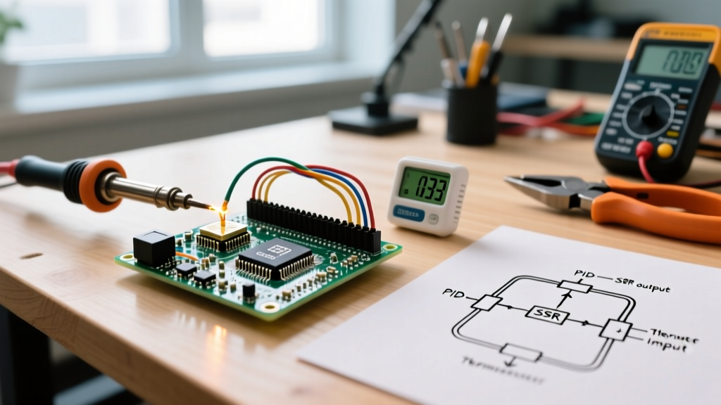

Rethinking the Arduino PID Temperature Controller Workflow
Building an Arduino PID temperature controller is a rite of passage for maker engineers, but the traditional workflow is often riddled with inefficiencies. Hobbyists and prototypers frequently spend dozens of hours battling integral windup, derivative kick, and high-frequency sensor noise. In 2026, with advanced thermal management requirements for everything from DIY reflow ovens to precision 3D printer hotends, relying on manual trial-and-error tuning is no longer viable.
Workflow optimization in thermal control means shifting from reactive debugging to proactive architecture. By selecting the right sensor amplification, implementing Time Proportioning Control (TPC) for Solid State Relays (SSRs), and leveraging the Åström-Hägglund relay-feedback auto-tuning method, you can reduce your development cycle from weeks to a single afternoon. This guide details a streamlined, professional-grade workflow for deploying robust PID thermal systems using standard microcontrollers.
Phase 1: Hardware Selection and Noise Mitigation
The most common point of failure in an Arduino PID workflow is noisy sensor data. If your derivative term (Kd) is amplifying high-frequency noise, your tuning workflow will stall. Selecting the right thermocouple amplifier and implementing proper grounding is the first step to a frictionless workflow.
Sensor Amplifier Comparison Matrix
| Amplifier IC | Thermocouple Type | Resolution | Fault Detection | Est. Price (2026) | Workflow Impact |
|---|---|---|---|---|---|
| MAX6675 | K-Type | 0.25°C | Basic (Open only) | $8 - $11 | High friction; lacks short-circuit detection, leading to silent failures. |
| MAX31855 | K, J, T, E, N | 0.25°C | Advanced (Open, Short to GND/VCC) | $14 - $18 | Optimized; built-in fault flags allow immediate code-level failsafes. |
| MAX31865 | PT100 / PT1000 (RTD) | 0.01°C | Advanced (RTD wiring faults) | $16 - $22 | Precision workflow; ideal for laboratory-grade thermal stability under 600°C. |
Expert Insight: For most general-purpose heating applications up to 400°C, the MAX31855 breakout board offers the best balance of cost and workflow efficiency. Its SPI interface is non-blocking compared to analog ADC reads, and its hardware-level fault detection eliminates the need to write complex software-based anomaly filters.
Wiring for EMI Reduction
When driving inductive loads or using high-wattage AC heating elements via an SSR, electromagnetic interference (EMI) will corrupt your SPI or analog lines. To optimize your physical workflow:
- Twisted Pairs: Always use shielded twisted-pair cable for the thermocouple probe. Ground the shield at the Arduino ground plane, not at the thermocouple tip.
- Zero-Crossing SSRs: Use a zero-crossing SSR like the Fotek SSR-25DA ($9-$12). By switching the AC load only at the zero-voltage crossing, you drastically reduce the high-frequency EMI spikes that typically corrupt microcontroller ADC readings.
Phase 2: Streamlined Code Architecture
A major bottleneck in PID development is writing inefficient loop structures. Thermal systems have high inertia; a heating element and aluminum block do not change temperature in milliseconds. Therefore, running your PID calculation inside a tight while() loop or using delay() wastes CPU cycles and introduces derivative noise.
Implementing Time Proportioning Control (TPC)
Standard PWM (Pulse Width Modulation) operates at roughly 490Hz on most Arduino pins. Switching a mechanical relay or even an SSR at 490Hz will destroy the component and generate massive electrical noise. Instead, optimize your workflow by implementing Time Proportioning Control (TPC) with a window size of 1000ms to 5000ms (1Hz to 0.2Hz).
// TPC Workflow Snippet
int windowSize = 2000; // 2-second control window
unsigned long windowStartTime = millis();

void loop() {
  // ... read sensor, compute PID ...

  if (millis() - windowStartTime > windowSize) {
    windowStartTime += windowSize; // Time to shift the window
  }

  if (Output < (millis() - windowStartTime)) {
    digitalWrite(SSR_PIN, LOW); // Heater OFF
  } else {
    digitalWrite(SSR_PIN, HIGH); // Heater ON
  }
}
By pairing TPC with the SetSampleTime(250) function in Brett Beauregard’s standard PID library, you instruct the microcontroller to only recalculate the PID math every 250 milliseconds. This stabilizes the derivative term and frees up the MCU to handle serial logging, display rendering, and network telemetry without interrupting the thermal control loop.
Phase 3: Accelerated Tuning via Relay-Feedback
Manual Ziegler-Nichols tuning—where you manually increase Kp until the system oscillates—is dangerous for high-power heating elements and incredibly time-consuming. To optimize your workflow, utilize the Åström-Hägglund relay-feedback method via the Arduino-PID-AutoTune-Library.
The Auto-Tune Workflow Step-by-Step
- Initialize the AutoTune Object: Set the target setpoint and the output step size (e.g., forcing the heater to 100% ON and 0% OFF).
- Run the Relay-Feedback Loop: The library automatically toggles the heater based on the current temperature crossing the setpoint, forcing a stable, safe oscillation.
- Extract Ultimate Gain (Ku) and Period (Pu): Once the library detects consistent oscillations (usually after 5-10 cycles), it calculates the ultimate gain and period.
- Apply Ziegler-Nichols Rules: The library automatically outputs the optimal Kp, Ki, and Kd values based on your chosen tuning rule (e.g., Ziegler-Nichols, Tyreus-Luyben).
Workflow Pro-Tip: Before running the Auto-Tune routine, manually heat your system to within 10°C of your target setpoint. Auto-tuning from room temperature can trigger integral windup or safety shutoffs before the oscillation phase begins. Starting near the setpoint reduces the auto-tune phase from hours to roughly 20 minutes.
Phase 4: Edge Cases and Failsafe Implementation
An optimized workflow anticipates failure modes before they result in burned components or ruined batches. A robust Arduino PID temperature controller must handle sensor disconnects and runaway thermal conditions gracefully.
Critical Failsafes to Include in Your Sketch
- Sensor Disconnect Fault: If using the MAX31855, check the fault register. If the IC returns
0x7FFF(thermocouple open circuit), immediately bypass the PID loop and force the SSR pinLOW. - Maximum Runaway Timer: Implement a software watchdog. If the PID output is at 100% for longer than a calculated thermal mass threshold (e.g., 3 minutes) and the temperature has not risen by at least 5°C, trigger an emergency shutoff. This catches failed SSRs that have shorted internally to the "ON" state.
- Derivative Kick Mitigation: Ensure your PID library is configured to use "Derivative on Measurement" rather than "Derivative on Error." As detailed in Brett Beauregard's definitive PID guide, calculating the derivative based on the setpoint causes massive output spikes whenever the user changes the target temperature, which can trip hardware overcurrent protections.
Summary of Workflow Gains
Transitioning from a naive PID implementation to an optimized workflow yields massive dividends in project turnaround time. By utilizing SPI-based fault-detecting sensors, implementing Time Proportioning Control to protect your switching hardware, and leveraging automated relay-feedback tuning, you eliminate the guesswork from thermal management. This structured approach ensures your Arduino PID temperature controller is not just functional, but industrially robust, repeatable, and ready for 24/7 deployment.