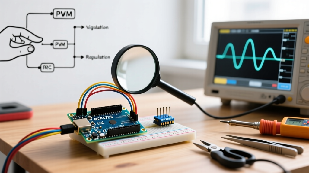

The Core Misconception: PWM vs. True Analog Voltage
When makers attempt to generate an analog output from Arduino boards, they almost universally hit a hardware wall: classic AVR-based boards like the Uno R3 and Nano do not possess a true Digital-to-Analog Converter (DAC). Instead, the analogWrite() function generates a Pulse Width Modulation (PWM) square wave. If you are troubleshooting erratic motor behavior, flickering LEDs, or incorrect sensor biasing, you are likely dealing with PWM ripple or I2C DAC configuration errors.
In 2026, the maker ecosystem has expanded significantly. While the Arduino Uno R4 Minima finally introduced a true 12-bit DAC on pin A0, millions of legacy boards and external DAC modules like the MCP4725 remain in active use. This guide provides deep-level troubleshooting for both PWM smoothing and external DAC failures.
Diagnostic Matrix: Identifying Your Analog Failure
Before grabbing a soldering iron, match your symptom to the root cause using the matrix below.
| Symptom | Measurement / Observation | Root Cause | Hardware / Code Fix |
|---|---|---|---|
| Motor stutters or whines at low speeds | Oscilloscope shows 5V square wave, not flat DC | PWM frequency too low; no filtering | Add RC low-pass filter or switch to true DAC |
| DAC outputs 0V or VCC constantly | I2C scanner finds no devices on bus | Missing pull-up resistors or wrong address | Add 4.7kΩ pull-ups; check ADR pin state |
| Max output voltage is only 3.3V on a 5V system | Multimeter reads 3.28V at max code (255/4095) | DAC VREF tied to 3.3V logic rail | Tie DAC VDD/VREF to 5V rail |
| Output wraps around or clips unexpectedly | Code sends 1023, but output behaves like 255 | Resolution mismatch (8-bit vs 10/12-bit) | Map values or use board-specific DAC functions |
Scenario A: Smoothing PWM into True DC (RC Filter Design)
If you are restricted to an ATmega328P-based board and need a stable DC voltage for an op-amp reference or a 0-10V industrial control signal, you must filter the PWM. The standard Arduino Uno PWM pins operate at two distinct frequencies: pins 5 and 6 run at ~980 Hz, while pins 9, 10, and 11 run at ~490 Hz.
Calculating the RC Low-Pass Filter
A simple first-order RC filter will convert the square wave into a usable DC voltage, provided the cutoff frequency ($f_c$) is significantly lower than the PWM frequency. The formula is:
$f_c = 1 / (2 π R C)$
For a 490 Hz PWM signal (Pin 9), targeting a cutoff frequency of roughly 15 Hz ensures minimal ripple while maintaining a reasonable response time. Using a 10kΩ resistor and a 1 μF capacitor yields a cutoff of 15.9 Hz.
- Response Time: The output will take roughly $3 × R × C$ (30 milliseconds) to settle to within 95% of the target voltage.
- Impedance Warning: A 10kΩ output impedance is too high to drive a low-impedance load directly. You must buffer the output using an op-amp configured as a voltage follower (e.g., LM358 or MCP6001) to prevent the load from pulling the voltage down.
Expert Tip: Never use an unfiltered PWM signal to drive analog measurement equipment or electrochemical cells. The high-frequency AC component can cause permanent degradation or false readings in sensitive instrumentation.
Scenario B: Debugging External I2C DACs (MCP4725)
When true analog output from Arduino is mandatory, the Microchip MCP4725 12-bit DAC is the industry-standard breakout module (typically priced around $3.50 to $5.00 for generic clones, or $9.95 for the official Adafruit 935 module). Troubleshooting I2C DACs requires verifying three distinct hardware layers.
1. I2C Address Conflicts and Pull-Up Resistors
The MCP4725 default I2C address is 0x60. If the ADR pin on the breakout is pulled high to VDD, the address shifts to 0x62. A common failure mode on cheap clone modules is the omission of I2C pull-up resistors. The ATmega328P internal pull-ups (roughly 30kΩ) are far too weak for reliable I2C communication at 400 kHz.
- The Fix: Solder 4.7kΩ resistors between SDA and VCC, and SCL and VCC on your breadboard or shield.
2. VDD and VREF Mismatches
The MCP4725 uses its VDD pin as the voltage reference. If you are powering the module from the Arduino's 3.3V pin to interface with an ESP32, your maximum analog output will be capped at 3.3V, even if your target circuit expects a 0-5V range. Ensure the DAC VDD matches the required analog output ceiling, and use a logic level converter (like the BSS138-based bi-directional shifters) for the I2C data lines if mixing 3.3V and 5V domains.
Scenario C: Architecture Resolution Clashes
A frequent software bug occurs when migrating code between different microcontroller families. The analogWrite() function behaves differently depending on the silicon.
Resolution Comparison Matrix
| Microcontroller | Board Example | Resolution | Value Range | Hardware Feature |
|---|---|---|---|---|
| ATmega328P | Uno R3, Nano | 8-bit | 0 - 255 | PWM only (Timer-based) |
| ESP32-WROOM | NodeMCU-32S | 8-bit (Default Core) | 0 - 255 | LEDC PWM (Configurable up to 14-bit) |
| ATSAMD21 | Zero, MKR | 10-bit | 0 - 1023 | True DAC on A0 |
| Renesas RA4M1 | Uno R4 Minima | 12-bit | 0 - 4095 | True DAC on A0 |
If you port a sketch from an Arduino Due (12-bit, 0-4095) to a classic Nano (8-bit, 0-255), sending a value of 4095 to analogWrite() will result in an integer overflow or bitwise truncation, often defaulting to 255 (100% duty cycle) regardless of your intended mid-range voltage. Always use the map() function or conditional compilation macros to handle resolution scaling across different architectures.
Hardware Verification Protocol: Multimeter Debugging
When code and wiring appear correct, rely on a True-RMS digital multimeter (such as the Brymen BM235 or Fluke 87V) to isolate the fault. Follow this exact sequence:
- Measure the Reference Rail: Probe the VREF or VDD pin of your DAC/filter. If it reads 4.6V instead of 5.0V, your USB cable or onboard regulator is sagging under load. The analog output will never reach the expected maximum.
- Switch to AC+DC Mode: Standard DC voltage mode on a multimeter will average out a PWM signal, giving a false sense of a 'smooth' analog voltage. Switch your meter to AC voltage mode. If you read a significant AC voltage (e.g., 1.5V AC) on your supposed 'DC' analog output, your RC filter capacitor is either missing, undersized, or suffering from high Equivalent Series Resistance (ESR) degradation.
- Check Ground Loops: Ensure the ground of the Arduino, the DAC module, and the target actuator share a common, low-impedity ground plane. A floating ground between an external power supply and the Arduino will cause the analog output to float erratically relative to the load.
Summary
Achieving a clean, reliable analog output from Arduino hardware requires understanding the physical limitations of your specific board. Whether you are designing a precise RC filter to tame ATmega PWM ripple, configuring pull-ups for an MCP4725 I2C DAC, or managing 12-bit resolution mappings on the newest Renesas-based boards, systematic hardware verification is the key to stable voltage control. Always validate your analog signals with True-RMS measurement tools to catch the high-frequency noise that standard code debugging simply cannot see.