
Arduino A to D Converter: Quick Reference Matrix
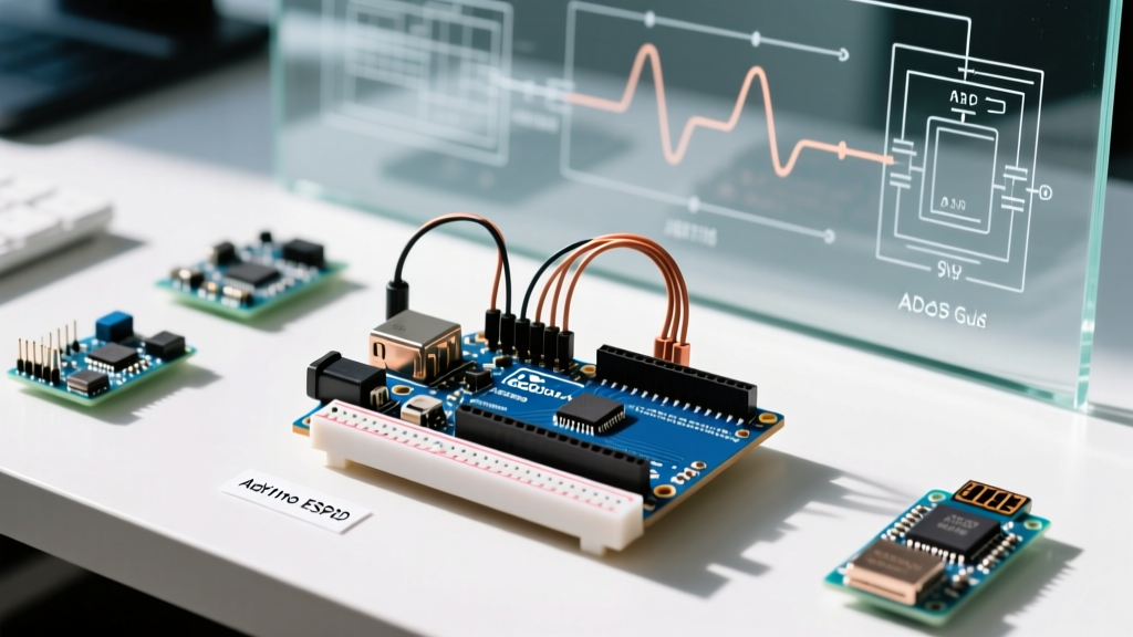
Before diving into specific troubleshooting scenarios, it is critical to understand the hardware limitations of the microcontroller you are using. The term "Arduino A to D converter" usually refers to the internal ADC of the ATmega328P, but modern maker projects frequently incorporate ESP32 boards or external I2C/SPI chips to bypass internal silicon limitations.
| Microcontroller / IC | Resolution | Channels | Max Sampling Rate | Typical Breakout Cost (2026) |
|---|---|---|---|---|
| ATmega328P (Uno/Nano) | 10-bit (1024 steps) | 6 (A0-A5) | ~15 kSPS | N/A (Internal) |
| ESP32 (Standard) | 12-bit (4096 steps) | 15 (ADC1/ADC2) | ~200 kSPS | N/A (Internal) |
| Texas Instruments ADS1115 | 16-bit (65536 steps) | 4 (Mux) | 860 SPS | $4.50 - $8.00 |
| Microchip MCP3008 | 10-bit (1024 steps) | 8 (Mux) | 200 kSPS | $2.50 - $4.00 |
Frequently Asked Questions (FAQ)
1. What exactly is the resolution of the standard Arduino A to D converter?
The standard Arduino Uno (ATmega328P) features a 10-bit Successive Approximation Register (SAR) ADC. This means it maps input voltages between 0V and the reference voltage (default 5V) into integer values between 0 and 1023. This yields a voltage resolution of approximately 4.88 mV per step (5.0V / 1024). If you are measuring a thermocouple or a load cell where millivolt precision is required, the internal ADC will introduce significant quantization error. According to Analog Devices' MT-001 Tutorial, quantization noise is an inherent limitation of fixed-bit ADCs, necessitating external hardware for high-precision sensor interfacing.
2. Why are my analogRead() values fluctuating wildly?
Fluctuating ADC readings are the most common issue makers face. This is rarely a software bug and almost always a hardware noise or reference issue. Common culprits include:
- High Impedance Sources: The ATmega328P ADC requires a source impedance of 10kΩ or less to properly charge its internal sample-and-hold capacitor within the 1.5 ADC clock cycle acquisition time. If you are using a high-value voltage divider (e.g., 100kΩ resistors), the capacitor will not charge fully, resulting in erratic readings. Fix: Add a 100nF ceramic capacitor between the analog pin and GND, or use an op-amp voltage follower.
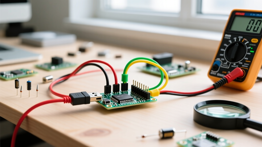
- Noisy VREF / USB Power: Powering the Uno via USB introduces high-frequency switching noise from the PC's power supply. Fix: Power the board via the barrel jack with a regulated 9V supply, or use the 3.3V pin as an external AREF.
- Missing Decoupling: Ensure a 100nF bypass capacitor is placed as close to the VCC and GND pins of your sensor as physically possible.
3. How do I change the analog reference voltage (AREF)?
By default, the Arduino uses the board's operating voltage (5V or 3.3V) as the reference. You can increase resolution for low-voltage sensors by switching to the internal 1.1V reference or supplying an external voltage to the AREF pin. Use the analogReference() function. As detailed in the official Arduino analogReference() documentation, you must never apply an analog input voltage higher than your selected AREF, or you risk damaging the internal multiplexer. Furthermore, always place a 100nF capacitor between the AREF pin and GND to stabilize the internal reference buffer.
4. When should I abandon the internal ADC for an external chip like the ADS1115?
You should upgrade to an external Arduino A to D converter module when your project demands:
- Higher Resolution: The TI ADS1115 provides 16-bit resolution (0.18mV per step at ±4.096V gain), which is mandatory for precise load cells or medical-grade biopotential sensors.
- Differential Measurements: Internal Arduino ADCs are single-ended (measured against GND). The ADS1115 allows differential measurements, rejecting common-mode noise—critical for industrial environments or long cable runs.
- ESP32 Non-Linearity Bypass: The ESP32's internal 12-bit SAR ADC is notoriously non-linear at the extremes of its range (below 0.1V and above 3.1V). If you need accurate rail-to-rail 3.3V measurements on an ESP32, an external I2C ADC is mandatory.
Quick-Start Wiring: Adding the ADS1115 via I2C
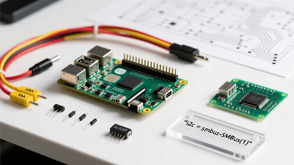
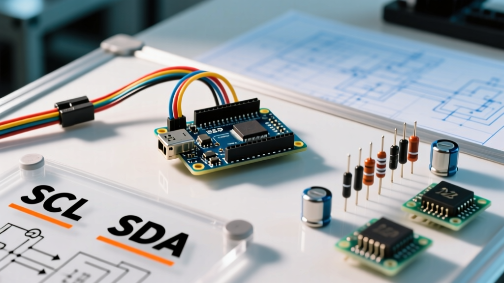
If you have determined that the internal ADC is insufficient, the ADS1115 is the industry-standard upgrade. Here is the quick-reference wiring matrix for connecting the Adafruit or SparkFun ADS1115 breakout to an Arduino Uno:
| ADS1115 Pin | Arduino Uno Pin | Notes |
|---|---|---|
| VDD | 5V | Can also use 3.3V for ESP32 logic compatibility |
| GND | GND | Ensure common ground with sensor |
| SCL | A5 (I2C SCL) | Use 4.7kΩ pull-up resistors if not on breakout |
| SDA | A4 (I2C SDA) | Default I2C address is 0x48 |
| ADDR | GND | Tie to VDD for 0x49, SDA for 0x4A, SCL for 0x4B |
Pro-Tip for 2026 Maker Setups: When using the ADS1115 with high-impedance sensors, enable the internal Programmable Gain Amplifier (PGA) via the Adafruit_ADS1X15 library. Setting the gain to GAIN_SIXTEEN maps the ±0.256V range to the full 16-bit spectrum, yielding an incredible 7.8µV per step resolution.
Calculating True Voltage from ADC Integer Output
A frequent point of confusion is the mathematical conversion from the raw ADC integer back to real-world voltage. The correct engineering formula for the ATmega328P is:
Voltage = (ADC_Value * VREF) / 1024.0
Notice the denominator is 1024, not 1023. The ADC has 1024 discrete quantization bins (numbered 0 through 1023). The value 1023 represents the voltage range from (1023/1024)*VREF up to VREF. Dividing by 1024 calculates the nominal voltage at the center of the quantization bin, minimizing systematic offset errors in data logging applications.
Advanced Troubleshooting: Edge Cases & Failure Modes
The "Ghost Voltage" Phenomenon on Unconnected Pins
If you read an unconnected analog pin, you will often see random, fluctuating values between 0 and 1023. This is not a broken Arduino A to D converter; it is the internal sample-and-hold capacitor picking up ambient electromagnetic interference (EMI) and crosstalk from adjacent digital traces. Always tie unused analog pins to GND via a 10kΩ resistor in high-noise environments, or simply ignore them in software.
ESP32 ADC2 Wi-Fi Collision
A frequent trap for developers migrating from the Uno to the ESP32 is the ADC2 hardware limitation. The ESP32's ADC2 pins share hardware resources with the Wi-Fi radio. If your sketch initializes WiFi.begin(), any subsequent calls to analogRead() on ADC2 pins (GPIO 0, 2, 4, 12-15, 25-27) will fail or return zero. Rule of thumb: Always route analog sensors to ADC1 pins (GPIO 32-39) on the ESP32 if Wi-Fi or Bluetooth is active.
Understanding the Nyquist Limit and Aliasing
The ATmega328P's maximum sampling rate of ~15 kSPS dictates that the highest frequency signal you can accurately measure is ~7.5 kHz, according to the Nyquist-Shannon sampling theorem. If you attempt to measure a 10kHz PWM signal or high-frequency audio waveform with the internal ADC, you will experience aliasing—where the high-frequency signal masquerades as a lower-frequency beat signal in your data. For audio or vibration analysis, you must use an external high-speed ADC or a dedicated DSP chip.
Protecting the ADC Input from Overvoltage
The internal ADC pins are directly connected to the microcontroller's silicon die. Applying a voltage even 0.5V above VCC will forward-bias the internal ESD protection diodes, potentially destroying the pin or the entire MCU. When interfacing with external environments (e.g., automotive 12V systems or industrial 24V PLCs), always use a hardware clamping circuit. A standard defense network includes a 10kΩ series resistor to limit diode current, paired with a 3.3V or 5.1V Zener diode tied to ground, ensuring the voltage at the ADC pin never exceeds the safe threshold regardless of transient spikes.
Oversampling for Software Resolution Gains
If you are stuck with a 10-bit internal ADC but need 12-bit precision, you can use software oversampling. By taking multiple samples and averaging them, you can mathematically reduce noise and increase effective resolution. The rule of thumb is that 4x oversampling yields 1 additional bit of resolution. To get 12 bits from a 10-bit ADC, you must sample 16 times, sum the results, and bit-shift right by 2 (divide by 4). Note that this reduces your effective sampling rate, making it unsuitable for high-frequency signals, but perfect for slow-moving environmental sensors like thermistors, LDRs, or soil moisture probes.