
The Legacy xmas lights arduino Bottleneck
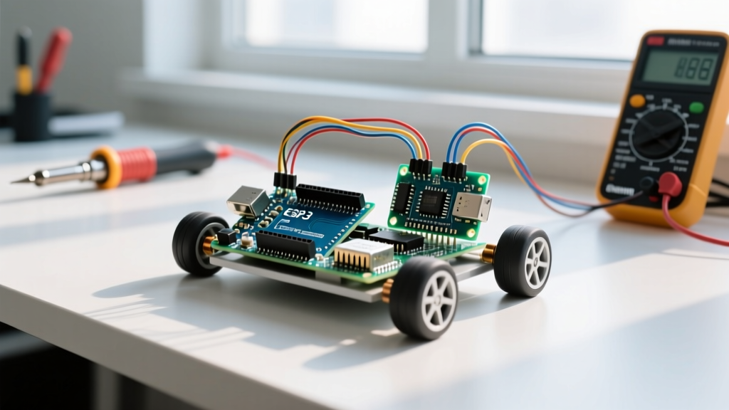
Building a custom xmas lights arduino controller is a rite of passage for every maker. If you built your display a few years ago, you likely used an Arduino Uno R3 (ATmega328P), a 5V 10A power brick, and a few hundred WS2812B LEDs driven by custom FastLED C++ sketches. While this setup is perfect for learning, it rapidly becomes a liability when scaling to rooflines, megatrees, or window matrices.
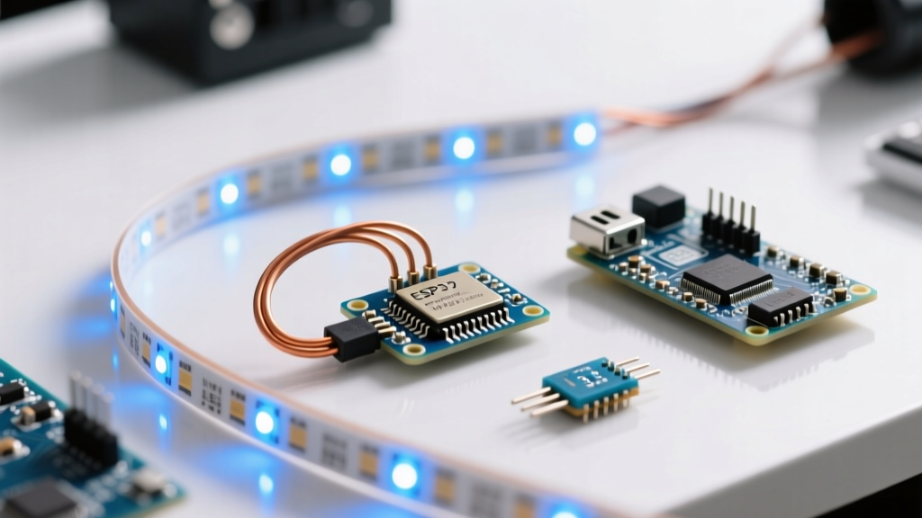
The ATmega328P is severely limited by its 2KB SRAM, capping your display at roughly 600 pixels before memory overflows cause random resets. Furthermore, 5V addressable strips suffer from massive voltage drops, requiring power injection every 50 pixels. As we move into the 2026 holiday season, the maker community has standardized on a vastly superior architecture: migrating to the ESP32-S3 microcontroller, 12V addressable LEDs, and the WLED firmware ecosystem.
Architecture Comparison: Legacy vs. 2026 Standard
Before tearing apart your existing enclosure, it is crucial to understand the hardware and software shifts required for this migration. The table below contrasts the classic Arduino Uno build with the modern ESP32-S3 standard.
| Feature | Legacy Arduino Uno (ATmega328P) | 2026 ESP32-S3 Migration |
|---|---|---|
| SRAM Capacity | 2 KB (Max ~600 pixels) | 512 KB (Supports 10,000+ pixels) |
| Connectivity | None (USB/Serial only) | Wi-Fi 4 & Bluetooth 5 (LE) |
| Logic Voltage | 5V (Native to WS2812B) | 3.3V (Requires Level Shifter) |
| Software Stack | Custom FastLED C++ sketches | WLED (Web UI, MQTT, E1.31 sync) |
| Controller Cost | ~$12 (Clone) to $27 (Genuine) | ~$8 (Lolin S3 Mini / QT Py) |
| LED Strip Standard | 5V WS2812B (High voltage drop) | 12V WS2815 (Backup data line) |
Step 1: Upgrading the Power Infrastructure
The most critical failure point in legacy builds is power distribution. Running 5V WS2812B strips over long distances results in severe voltage sag, turning white pixels pink or yellow at the end of the run. The modern solution is migrating to 12V WS2815 addressable LEDs.
Why WS2815?
- Lower Current Draw: A 12V WS2815 draws approximately 12mA per pixel at full white, compared to the 60mA draw of a 5V WS2812B. This drastically reduces the required wire gauge and power supply capacity.
- Backup Data Line (BI/DI): The WS2815 features a secondary data wire. If one pixel dies, the signal bypasses it and continues to the rest of the strip, preventing the "dead pixel cascade" that plagues older WS2812B setups.
- Extended Runs: You can reliably run 300 pixels from a single power injection point, compared to just 50 pixels on a 5V strip.
For a 1,000-pixel roofline setup, your maximum theoretical draw is 12A (1000 x 0.012A). To ensure longevity and prevent thermal throttling, operate your power supply at 80% capacity. A Mean Well LRS-150-12 (12V, 12.5A, ~$28) is the gold standard for this application. According to the Adafruit NeoPixel Überguide, you must use 18 AWG (or thicker) stranded copper wire for your main power injection lines to prevent wire heating and voltage drop.
Step 2: Controller Swap and 3.3V Logic Level Shifting
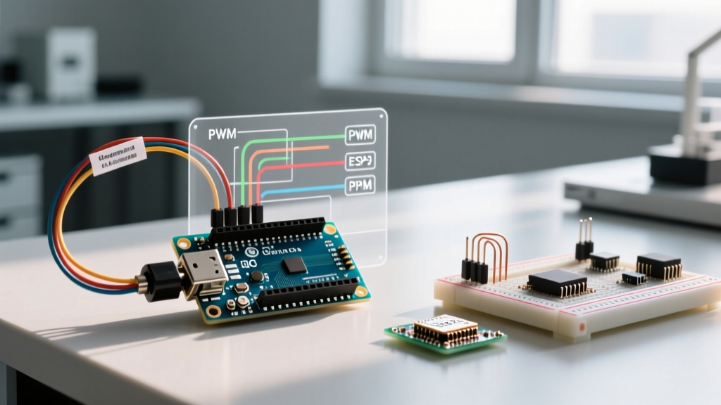
Migrating from the 5V Arduino Uno to a 3.3V ESP32-S3 introduces a hardware compatibility hurdle. The WS2815 data line requires a 5V logic signal to reliably read the high-speed 800kHz data stream. Feeding it 3.3V directly from the ESP32 will result in flickering, random color flashes, or complete signal failure.
The SN74AHCT125N Level Shifter
Do not use CD4050B or basic transistor-based shifters; they are too slow for addressable LED protocols. You must use a high-speed CMOS level shifter like the SN74AHCT125N or 74AHCT123 (~$1.50).
- VCC (Pin 14): Connect to a stable 5V source. (You can use the 5V output pin on your ESP32-S3 dev board, provided it is backed by a decent onboard regulator, or tap a dedicated 5V buck converter).
- GND (Pin 7): Connect to the common system ground.
- 1A (Pin 2): Connect to your chosen ESP32-S3 GPIO data pin (e.g., GPIO 2).
- 1Y (Pin 3): Connect to the DIN (Data In) pad on your WS2815 LED strip.
Critical Grounding Rule: The ESP32, the Level Shifter, the 12V Power Supply, and the LED strip must share a common ground. If you omit the ground wire between the ESP32 and the 12V PSU, the 3.3V data signal has no reference voltage, and the LEDs will behave erratically.
Step 3: Flashing WLED and Pin Mapping
Writing custom FastLED code for complex 2026 effects (like audio reactivity or multi-segment synchronization) is incredibly time-consuming. The community standard is now WLED, an open-source firmware that provides a local web interface, MQTT integration, and E1.31/sACN support for syncing multiple controllers.
Selecting the Right GPIO Pins
Not all pins on the ESP32-S3 are safe to use. Many pins are "strapping pins" used during boot to determine flash voltage or boot mode. If you use a strapping pin for LED data, your ESP32 may fail to boot, or the LEDs may flash uncontrollably during startup.
- Avoid: GPIO 0, 3, 45, and 46.
- Recommended Data Pins: GPIO 2, 16, 17, or 18.
- Recommended Relay Pin (for AC switching): GPIO 38.
Flash the latest WLED binary (v0.14.4 or newer) via the official WLED Web Installer using a Chromium-based browser. Once flashed, connect to the "WLED-AP" Wi-Fi network, input your home network credentials, and navigate to LED Preferences. Set the LED type to WS281x, input your total pixel count, and assign your chosen GPIO pin.
Physical Enclosures and Weatherproofing
Upgrading electronics is useless if moisture destroys them during a winter storm. Legacy builds often relied on cheap plastic Tupperware containers with silicone caulk, which traps condensation and causes PCB corrosion.
For the 2026 migration, use IP67-rated ABS junction boxes (approx. $6 each). Drill holes for your wires and use PG9 or PG11 cable glands ($1.50 each) to create a watertight seal around the power and data cables. Place a small desiccant silica gel pack inside the enclosure before sealing the lid to absorb any residual moisture trapped during assembly. If your LED strips are exposed to direct snow or ice, ensure you purchase IP67 silicone-tubed variants rather than IP65 nano-coated strips, as the nano-coating degrades under UV exposure and physical abrasion over multiple seasons.
Troubleshooting Common Migration Failures
Even with careful planning, migrations can encounter edge cases. Here is how to diagnose the most common issues:
- The "First Pixel is Green, Rest are Off" Bug: This almost always indicates a missing common ground between the ESP32 and the LED power supply. Verify your GND connections with a multimeter.
- Random Flickering at High Brightness: Your 5V power rail feeding the level shifter is browning out. When the LEDs draw high current, magnetic interference or voltage sag on the breadboard rails can corrupt the logic level shifter. Solder the level shifter directly to a dedicated 5V buck converter (like an LM2596 set to 5.1V) rather than relying on the ESP32 dev board's onboard 5V pin.
- Wi-Fi Drops in Cold Weather: Standard 2.4GHz Wi-Fi signals degrade when passing through ice or dense pine branches. Mount your ESP32 enclosure as close to the exterior wall of your house (near the router) as possible, and use a 5-meter data extension cable (using a differential RS485 transmitter/receiver pair for distances over 10 meters) to reach the display.
Conclusion
Migrating your legacy xmas lights arduino project to an ESP32-S3 and WLED ecosystem transforms a fragile, limited DIY experiment into a commercial-grade, scalable light show. By upgrading to 12V WS2815 strips, implementing proper 3.3V to 5V logic level shifting, and utilizing robust IP67 enclosures, your display will run flawlessly through the harshest winter conditions, all while being controllable from your smartphone.