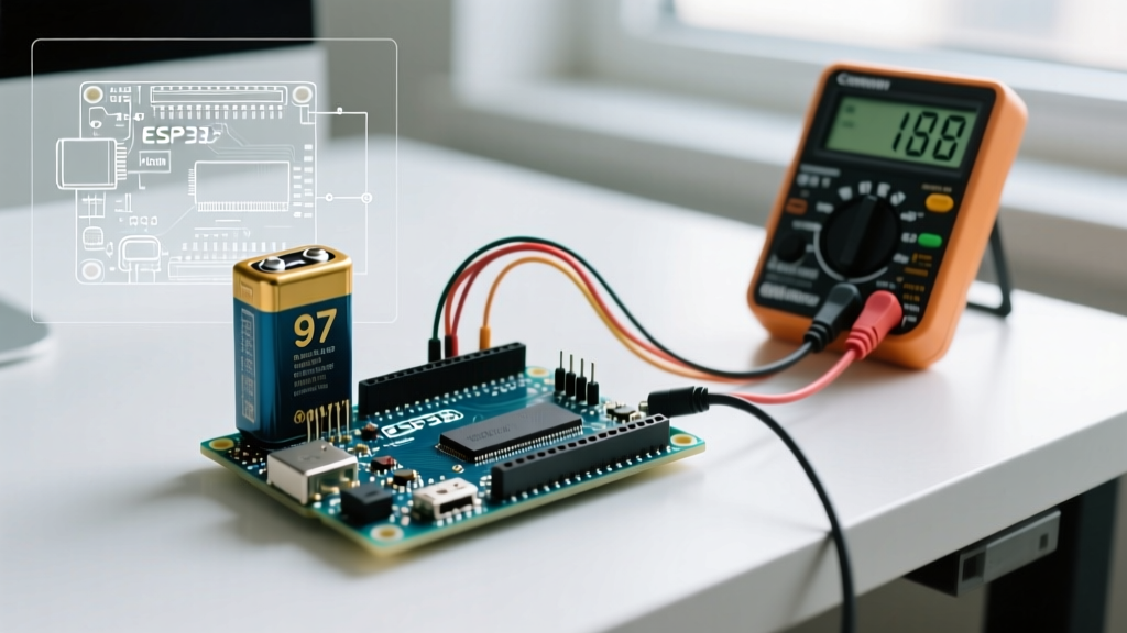

The Anatomy of a Battery-Powered Brownout
Transitioning an Arduino project from a stable USB power supply to battery power for Arduino deployments often introduces a host of phantom issues: random reboots, frozen I2C buses, and erratic analog readings. In 90% of cases, these are not software bugs but hardware-level voltage sags triggering the ATmega328P's Brown-out Detection (BOD) circuit. According to the official Microchip ATmega328P datasheet, the default BOD threshold on most standard Arduino Uno and Nano clones is set to 2.7V via the high fuse byte. If your 5V rail dips below this threshold for even a few microseconds, the microcontroller executes a hardware reset to prevent EEPROM corruption.
Standard digital multimeters (DMMs) sample at roughly 2-4 Hz, making them entirely useless for catching microsecond voltage sags caused by inductive loads. To properly troubleshoot battery power instability, you must understand the three primary failure modes: linear regulator thermal shutdown, high Equivalent Series Resistance (ESR) voltage sag, and backfeed ground loops.
Diagnosing Linear Regulator Thermal Shutdown
The most common mistake makers make when configuring battery power for Arduino is using a standard 9V PP3 alkaline battery connected to the barrel jack or Vin pin. The Arduino Uno Rev3 utilizes an NCP1117ST50T3G linear regulator. As detailed in the Arduino Uno Rev3 schematic, this regulator requires a minimum dropout voltage of 1.1V to maintain a stable 5V output, meaning it needs at least 6.1V at the input.
However, linear regulators dissipate excess voltage as heat. If your circuit draws 150mA (a typical draw for an Arduino, an I2C OLED, and a Wi-Fi module), the power dissipation becomes severe.
Table 1: Regulator Power Dissipation & Thermal Risk
| Battery Source (Vin) | Voltage Drop | Current Draw | Power Dissipation | SOT-223 Temp Rise |
|---|---|---|---|---|
| 6V (4x AA NiMH) | 1.0V | 150mA | 0.15W | +11°C (Safe) |
| 9V (PP3 Alkaline) | 4.0V | 150mA | 0.60W | +45°C (Hot) |
| 12V (Sealed Lead Acid) | 7.0V | 150mA | 1.05W | +78°C (Thermal Shutdown) |
When the junction temperature of the NCP1117 reaches approximately 160°C, its internal thermal protection kicks in, shutting down the 5V rail entirely. The Arduino resets, the regulator cools, it powers back on, and the cycle repeats, causing a continuous boot-loop that looks exactly like a software crash.
Battery Chemistry and Internal Resistance (ESR) Mismatches
Another critical failure point in battery power for Arduino setups is ignoring the internal resistance (ESR) of the chosen cell. When a peripheral like a 5V relay module or a micro-servo activates, it can draw a transient current spike of 500mA to 1A. Ohm's law dictates that V_sag = I_spike × ESR. If the ESR is too high, the battery voltage collapses instantly under load.
Table 2: Battery ESR and Transient Load Capability
| Battery Chemistry | Nominal Voltage | Typical ESR | Max Transient Draw (1 sec) | Verdict for Arduino |
|---|---|---|---|---|
| 9V Alkaline (PP3) | 9.0V | 1.5Ω - 2.5Ω | < 200mA | Poor (High Sag) |
| 4x AA NiMH (Eneloop) | 4.8V | 0.12Ω (total) | ~1.5A | Good (Low Sag) |
| 18650 Li-ion (Samsung 30Q) | 3.7V | 0.025Ω | 15A+ | Excellent (Requires Buck) |
| 2S LiPo (RC Hobby) | 7.4V | 0.015Ω | 20A+ | Excellent (High Efficiency) |
The Servo & Relay Voltage Sag Trap
If your Arduino resets precisely when a relay clicks or a servo moves, you are experiencing an inductive load transient. Servos like the TowerPro SG90 draw roughly 10mA at idle but can spike to 750mA when stalling or changing direction rapidly. If you are powering the servo directly from the Arduino's 5V pin, this current must flow through the board's thin PCB traces and the linear regulator (if powered via Vin).
The Fix: Never route high-current actuator power through the Arduino's onboard 5V rail. Use a dedicated synchronous buck converter (such as the Pololu D24V50F5) wired directly to the battery pack. Connect the buck converter's 5V output to the servo's power rail, and ensure the ground (GND) of the buck converter is tied directly to the Arduino's GND to maintain a common logic reference.
5 Actionable Fixes for Unstable Battery Power
If your battery-powered Arduino is resetting, freezing, or behaving erratically, follow this step-by-step diagnostic protocol to isolate and resolve the fault.
- Add Bulk and Decoupling Capacitance: Solder a 100µF low-ESR electrolytic capacitor (e.g., Panasonic FR series) and a 0.1µF ceramic capacitor in parallel across the 5V and GND pins on your breadboard or custom PCB. Place them within 5mm of the ATmega328P VCC pin to absorb high-frequency switching noise.
- Ditch the Linear Regulator: In 2026, using a linear regulator for battery-powered IoT is considered highly inefficient. Replace the onboard regulator workflow with a 3.3V or 5V switching buck converter. A modern buck converter operates at 85-95% efficiency, whereas the NCP1117 on an Arduino Uno operates at roughly 55% efficiency when stepping down 9V to 5V. This single change can double your 18650 battery life.
- Check for USB Backfeed: If your Arduino resets when you plug in the USB cable while the battery is also connected, the onboard Schottky diode (D1 on the Uno) might be failing, or you are using a cheap clone board lacking the diode entirely. This creates a ground loop and backfeeds 5V from the USB into the battery. Remove the battery before uploading code, or use a board with a proper power-path management IC like the Arduino Nano 33 IoT.
- Verify AVR Fuse Settings (BOD): If your battery voltage naturally droops as it depletes (e.g., a Li-ion dropping from 4.2V to 3.2V), and you are using a buck converter set to 4.5V, the BOD might trigger prematurely. Use AVRDUDE or the Arduino IDE's 'Burn Bootloader' function with a custom boards.txt entry to set the BOD to 1.8V or 2.7V, matching your actual minimum operating voltage.
- Measure with an Oscilloscope: If the resets persist, connect a digital storage oscilloscope (DSO) to the 5V rail and set the trigger to 'Dropout' mode at 4.8V. Capture the exact moment of the reset. If you see a sharp 500mV dip lasting 2µs, you have a trace inductance or decoupling issue. If you see a slow 2-second ramp down to 3V, your battery protection circuit (BMS) is tripping due to overcurrent.
Pro-Tip for Field Deployments: When logging data in remote locations, add a voltage divider (e.g., 100kΩ and 47kΩ) connected to an analog input to monitor the raw battery voltage in your sketch. Program the Arduino to write a 'Low Battery' flag to the EEPROM and enter deep sleep (via the watchdog timer) when the voltage drops below the safe threshold, preventing corrupted SD card writes during the final moments of battery life.