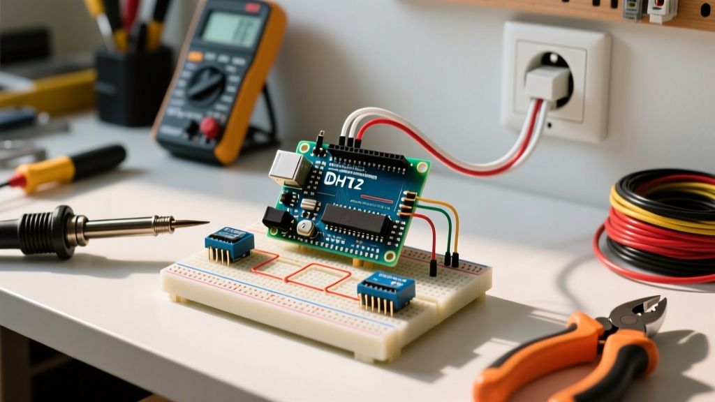

Why Build a Custom Thermostat with Arduino?
While commercial smart thermostats dominate the residential market, they often lack the flexibility required for custom maker projects. Whether you are automating a greenhouse climate control system, managing a reptile enclosure, or building a custom zoning solution for a workshop, building a thermostat with Arduino gives you absolute control over the logic, deadbands, and sensor placement. According to the U.S. Department of Energy, properly programmed thermostat setbacks can save up to 10% a year on heating and cooling. By rolling your own solution, you can implement hyper-specific schedules and multi-zone logic that off-the-shelf units simply cannot handle.
In this comprehensive guide, we will build a fully functional, isolated 24VAC-compatible heating and cooling controller. We will move beyond basic breadboard prototypes and focus on real-world edge cases, including back-EMF protection, optoisolation, and the critical concept of hysteresis to prevent equipment-destroying short-cycling.
Bill of Materials (BOM) and Component Selection
Selecting the right components is critical for long-term reliability. Avoid the DHT11 sensor; its 1°C resolution and inability to read below freezing make it useless for precise HVAC control. Instead, we use the DHT22 (AM2302).
| Component | Specific Model / Specification | Est. Price (2026) | Purpose |
|---|---|---|---|
| Microcontroller | Arduino Uno R3 (or ATmega328P clone) | $18.00 - $25.00 | Core logic and sensor polling |
| Temp Sensor | DHT22 (AM2302) with 10k Pull-up | $7.00 - $10.00 | High-precision ambient temp reading |
| Relay Module | 5V Dual-Channel Optocoupler (Songle SRD-05VDC) | $5.00 - $8.00 | Galvanic isolation and 24VAC switching |
| Power Supply | Hi-Link HLK-PM01 (24VAC to 5VDC Buck) | $6.00 - $9.00 | Derives 5V logic power from HVAC C & R |
| Protection | 1A Fast-Blow Fuses & Inline Holders | $3.00 | Prevents furnace board damage on shorts |
Critical HVAC Safety: Understanding 24VAC Logic
WARNING: Standard North American HVAC systems use 24VAC for control logic, which is generally safe for DIY wiring. However, the furnace control board is highly sensitive to short circuits. Accidentally bridging the 24VAC Hot (R) with the Common (C) or Ground will instantly blow the 3A automotive-style fuse on the furnace control board, or worse, destroy the board's trace pathways. Always use inline fuses on your custom thermostat wiring.
The R, W, Y, G, and C Wire Standard
To interface your Arduino thermostat with a standard HVAC system, you must understand the terminal designations:
- R (Red): 24VAC Hot (Power from the furnace transformer).
- C (Blue/Black): 24VAC Common (Return path for power).
- W (White): Heating Call. Connecting R to W engages the gas valve or heating elements.
- Y (Yellow): Cooling Call. Connects R to Y to engage the outdoor compressor contactor.
- G (Green): Fan Call. Connects R to G to run the indoor blower independently.
Step-by-Step Wiring Guide
For this tutorial, we will wire a single-stage heating system (R and W). The relay module acts as a dry-contact switch, mimicking the physical mercury switch or mechanical relay inside a traditional thermostat.
- Powering the Arduino (The HLK-PM01 Method): Connect the 24VAC R wire to the AC input (pin 1) of the HLK-PM01, and the 24VAC C wire to the AC input (pin 2). The DC output pins will provide a clean, isolated 5V and GND. Connect these to the Arduino's 5V and GND pins. Do not use the Arduino's onboard voltage regulator for 24VAC; it will explode.
- Wiring the DHT22 Sensor: Connect the DHT22 VCC to the Arduino 5V, and GND to Arduino GND. Connect the Data pin to Arduino Digital Pin 2. Crucial: You must solder a 10kΩ pull-up resistor between the VCC and Data pins, or the sensor will return
NaN(Not a Number) errors due to floating logic levels. - Wiring the Optocoupler Relay: Connect the Relay VCC to Arduino 5V, and GND to Arduino GND. Connect the IN1 control pin to Arduino Digital Pin 8. Wire the HVAC R wire to the Relay's COM (Common) terminal, and the HVAC W wire to the NO (Normally Open) terminal.
Why Optoisolation is Non-Negotiable
Cheap relay modules often share a common ground between the low-voltage logic side and the high-voltage load side. When the relay coil collapses, it generates a back-EMF spike. Without an optocoupler (like the PC817 found on quality Songle modules), this spike travels back through the ground line and resets or permanently damages the ATmega328P microcontroller. Always verify your module has optical isolation and separate jumper pins for logic and load power.
Programming the Hysteresis Loop
The most common mistake beginners make when coding a thermostat with Arduino is using a single setpoint (e.g., if (temp < 72) turnOn(); else turnOff();). If the room temperature hovers exactly at 71.9°F, the relay will click on and off multiple times per second. This is called short-cycling, and it will rapidly destroy your HVAC contactors and burn out compressor windings.
To prevent this, we implement hysteresis (a deadband). According to Adafruit's DHT Sensor Documentation, the DHT22 has an accuracy of ±0.5°C, meaning minor fluctuations are expected. We program a 2°F deadband:
- Target Setpoint: 72°F
- Heat ON Threshold: 71°F (Setpoint - 1°F)
- Heat OFF Threshold: 73°F (Setpoint + 1°F)
In your Arduino sketch, maintain a state variable:
bool isHeating = false;
float setpoint = 72.0;
float deadband = 1.0;

void loop() {
  float currentTemp = dht.readTemperature(true); // Read as Fahrenheit

  if (!isHeating && currentTemp < (setpoint - deadband)) {
    digitalWrite(RELAY_PIN, LOW); // Active LOW relay
    isHeating = true;
  }
  else if (isHeating && currentTemp >= (setpoint + deadband)) {
    digitalWrite(RELAY_PIN, HIGH);
    isHeating = false;
  }

  delay(2000); // DHT22 requires 2s between reads
}
The 5-Minute Compressor Delay (For Cooling)
If you expand this project to include the Y (Cooling) wire, you must implement a software timer that prevents the AC compressor from restarting for at least 5 minutes after shutting off. This allows the refrigerant pressures to equalize. Attempting to start a compressor against high head pressure will trip the thermal overload switch or stall the motor.
Real-World Troubleshooting and Edge Cases
Even with perfect wiring, environmental factors can disrupt your DIY thermostat. Here are the most common failure modes and their solutions:
- DHT22 Returns
NaNor 999°C: This is almost always a missing pull-up resistor or a data wire longer than 2 meters. The 1-Wire style protocol requires a strong 10kΩ pull-up to VCC. If running the sensor remotely, use a shielded twisted-pair cable (like Cat5e) and solder the pull-up resistor directly at the sensor head, not at the Arduino. - Arduino Randomly Resetting: This indicates a ground loop or back-EMF spike. Ensure your relay module is truly optoisolated. If using a mechanical relay without a built-in flyback diode, solder a 1N4007 diode in reverse bias across the relay coil terminals to absorb the inductive spike.
- Furnace Blows Cold Air on Heat Call: Some modern high-efficiency furnaces require a specific sequence or use proprietary communicating protocols (like Carrier Infinity or Lennox iComfort) rather than standard 24VAC dry contacts. Verify your furnace control board has standard R/W/Y/G/C terminals before wiring.
- Temperature Reads Too High: The Arduino's voltage regulator and the HLK-PM01 both emit heat. If the DHT22 is mounted in the same enclosure as the power supply and microcontroller, it will read the internal ambient heat. Use a ventilated enclosure or mount the sensor on a short pigtail outside the main junction box.
Summary
Building a smart thermostat with Arduino bridges the gap between software logic and high-stakes physical environmental control. By prioritizing galvanic isolation via optocouplers, utilizing the precise DHT22 sensor, and strictly programming hysteresis deadbands, you create a system that is not only functional but safe for your expensive HVAC equipment. Whether you are optimizing a residential setup or controlling an industrial incubator, mastering these fundamental microcontroller-to-relay concepts is a cornerstone skill for any advanced maker.