
The Anatomy of a Failing Thermistor Circuit
Integrating a thermistor and Arduino microcontroller is a rite of passage for environmental monitoring, 3D printer hotends, and DIY incubators. The standard 10K NTC 3950 thermistor is cheap, widely available, and reasonably accurate. However, makers frequently encounter a frustrating triad of issues: wildly fluctuating analog readings, consistent temperature offsets, and severe non-linear drift at temperature extremes. These are rarely defective components; they are systemic circuit and mathematical flaws.
In this comprehensive troubleshooting guide, we will diagnose the exact failure modes of NTC thermistor voltage dividers. We will move beyond basic tutorials and explore the electrical engineering principles required to stabilize your analog-to-digital converter (ADC) readings, eliminate self-heating artifacts, and implement the correct Steinhart-Hart mathematical models for professional-grade accuracy.
Symptom 1: Wildly Fluctuating ADC Readings (The Noise Problem)
If your serial monitor shows the temperature jumping by 2°C to 5°C between consecutive analogRead() calls, you are experiencing high-frequency ADC noise. This is especially prevalent when using older 8-bit AVR boards like the Arduino Uno R3 or Nano.
Root Cause: Impedance Mismatch and EMI
The ATmega328P microcontroller features a 10-bit ADC with a sample-and-hold (S/H) capacitor inside the multiplexer. According to the Arduino Official Documentation, the ADC is optimized for analog signals with an output impedance of approximately 10 kΩ or less. A standard 10K thermistor paired with a 10K pull-down resistor creates a Thevenin equivalent impedance that varies with temperature. At extreme cold, the thermistor's resistance can exceed 100 kΩ, starving the internal S/H capacitor of the charge it needs to settle before the conversion completes. Furthermore, long unshielded jumper wires act as antennas, picking up 50/60Hz mains hum and high-frequency switching noise from nearby PWM loads.
The Hardware Fix: Low-Pass RC Filtering
Do not rely solely on software averaging to fix hardware noise. You must stabilize the voltage at the analog pin before the ADC samples it.
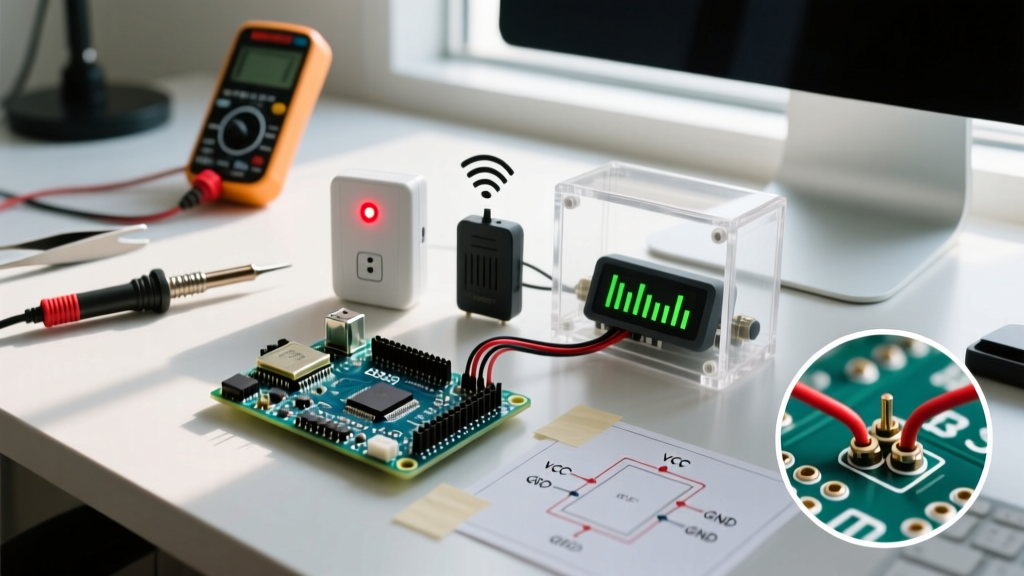
- Capacitor Selection: Solder a 0.1µF (100nF) X7R ceramic capacitor directly between the analog input pin and the microcontroller's GND. Place it as physically close to the MCU pin as possible.
- Wiring Topology: If your thermistor is located more than 12 inches from the Arduino, use twisted-pair wire (such as stripped Cat5e Ethernet cable) for the signal and ground lines to reject common-mode electromagnetic interference (EMI).
Symptom 2: Consistent Temperature Offset (The Self-Heating Trap)
Your readings are stable, but the thermistor consistently reports a temperature 1.5°C to 3.0°C higher than your calibrated reference thermometer. This is the self-heating effect, and it is a direct result of poor voltage divider design.
Root Cause: Joule Heating in the Bead
Every NTC thermistor has a dissipation constant ($\delta$), typically rated around 1.5 mW/°C in still air. This means for every 1.5 milliwatts of power dissipated inside the thermistor bead, its internal temperature will rise by 1°C above the ambient environment. If you wire a 10K thermistor to 5V with a 10K pull-down resistor, the current flowing through the circuit at 25°C is roughly 0.25 mA. The power dissipated by the thermistor is $P = I^2R$, which equals 0.625 mW. While this seems small, in a stagnant air environment, it easily induces a 0.4°C to 0.8°C permanent offset.
The Fix: Duty Cycling and Resistor Scaling
To eliminate self-heating without sacrificing signal resolution, implement the following modifications:
- Upgrade the Pull-Down Resistor: Swap the 10K pull-down resistor for a 47K or 100K precision metal film resistor (1% tolerance). This drastically reduces the continuous current flow while still providing a usable voltage swing for the ADC.
- Implement Power Duty Cycling: Instead of wiring the top of the voltage divider to the continuous 5V rail, wire it to a digital I/O pin (e.g., Pin 8). Set the pin to
OUTPUTand pull itHIGHonly 15 milliseconds before taking youranalogRead(), then immediately pull itLOW. This reduces the average power dissipation to near zero.
Symptom 3: Non-Linear Drift at Extremes (The Math Fallacy)
Your circuit is perfectly quiet, and self-heating is eliminated. Yet, while the sensor is accurate at room temperature (25°C), it reads 4°C too low when placed in a freezer (-18°C) and 6°C too high in boiling water.
Root Cause: The Beta Parameter Equation Limitation
Most basic Adafruit and maker tutorials teach the simplified Beta ($\beta$) parameter equation. The Beta equation assumes a perfectly linear relationship between the logarithm of resistance and the inverse of temperature. In reality, NTC thermistors are highly non-linear. The Beta value (usually 3950) is only an average slope calculated between 25°C and 50°C. Applying it outside this narrow band guarantees massive mathematical drift.
The Fix: Steinhart-Hart Implementation
For a wide operational range (-40°C to +125°C), you must use the third-order Steinhart-Hart equation. This requires three specific coefficients (A, B, and C) derived from the manufacturer's resistance-temperature (R-T) table. For a standard 10K NTC 3950 thermistor, the coefficients are:
- A: 0.001129148
- B: 0.000234125
- C: 0.0000000876741
By implementing the full cubic equation in your sketch, you will reduce the mathematical error to less than ±0.15°C across the entire usable range of the sensor.
Quick-Reference Diagnostic Matrix
Use the table below to quickly isolate your specific thermistor and Arduino integration issue based on serial monitor behavior and physical circuit conditions.
| Symptom Profile | Primary Root Cause | Hardware Intervention | Software Intervention |
|---|---|---|---|
| Rapid, random ±3°C jumps | High source impedance / EMI | Add 0.1µF cap to GND; use twisted pair | Implement 16x oversampling moving average |
| Stable, but reads +1.5°C high | Joule self-heating | Switch to 47K pull-down resistor | Duty-cycle the voltage divider power pin |
| Accurate at 25°C, wrong at extremes | Beta equation non-linearity | N/A (Mathematical error) | Replace Beta math with Steinhart-Hart |
| Reads exactly 1023 or 0 always | Wiring fault / Blown trace | Check continuity; verify common ground | Verify correct analog pin mapping in IDE |
Advanced Oversampling for the Arduino Uno R4
If you have upgraded to the Arduino Uno R4 Minima or WiFi, you are working with the Renesas RA4M1 ARM Cortex-M4 processor. This MCU boasts a 14-bit ADC (16,384 discrete steps) compared to the R3's 10-bit ADC (1,024 steps). While the 14-bit resolution provides incredible granularity, it also makes the ADC hyper-sensitive to microscopic thermal noise and breadboard contact resistance.
Expert Insight: When using a 14-bit ADC with a high-impedance thermistor, never rely on a single analogRead(). The internal sampling capacitor requires precise timing to charge fully. Always discard the first reading after switching multiplexer channels, as it will contain ghost voltage from the previous pin.
Below is a highly optimized C++ function for the Uno R4 that discards the first sample, takes 16 subsequent readings, and applies a bit-shifting average to extract a stable, high-resolution temperature value without floating-point math overhead.
// Optimized 14-bit ADC Oversampling for NTC Thermistor
uint16_t readStableThermistor(uint8_t analogPin) {
  // Set pin as input and allow MUX to settle
  pinMode(analogPin, INPUT);
  delayMicroseconds(50);

  // Discard the first 'ghost' reading
  analogRead(analogPin);

  uint32_t sum = 0;
  // Take 16 samples for oversampling
  for (uint8_t i = 0; i < 16; i++) {
    sum += analogRead(analogPin);
    delayMicroseconds(100); // Allow S/H cap to recharge
  }

  // Bit-shift right by 4 (divide by 16) to get the true 14-bit average
  return (uint16_t)(sum >> 4);
}
Final Calibration and Deployment
Even with perfect hardware filtering and the Steinhart-Hart equation, manufacturing tolerances mean your specific 10K thermistor might have a base resistance of 9.8K or 10.2K at exactly 25°C. For mission-critical applications like sous-vide cooking or reptile terrarium control, perform a two-point physical calibration. Submerge the thermistor in an ice-water bath (0°C) and a temperature-controlled water bath at 50°C. Record the raw ADC values and calculate a linear offset correction factor in your sketch. By combining rigorous hardware filtering, self-heating mitigation, and advanced mathematical modeling, your thermistor and Arduino project will deliver laboratory-grade reliability in any environment.