
The Hidden Cost of Floating Pins in Rapid Prototyping
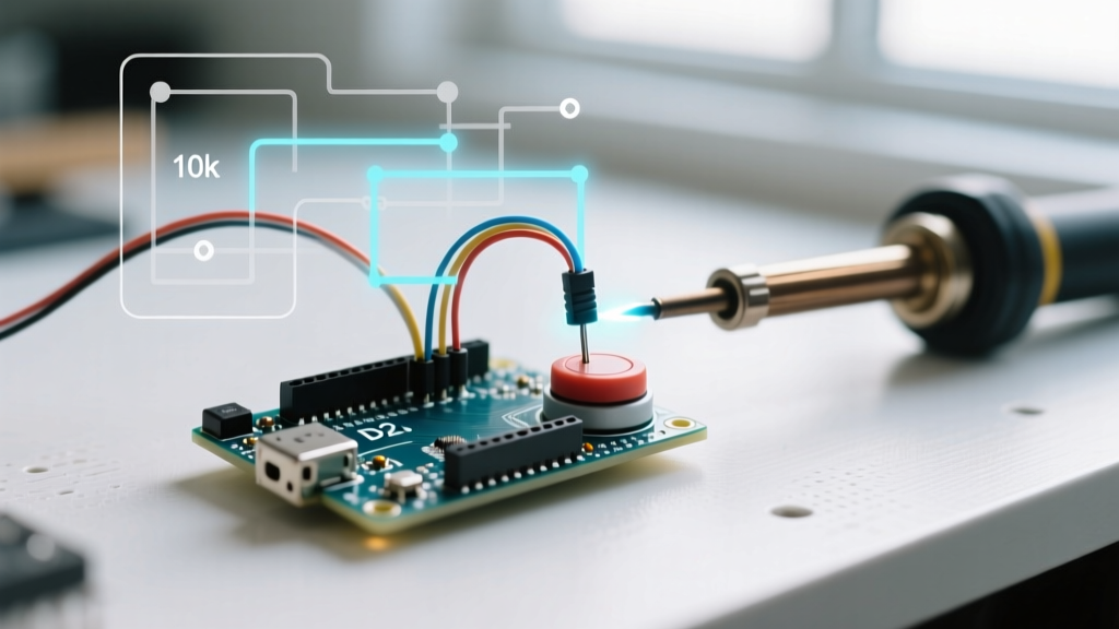
Every embedded systems engineer and maker has experienced the phantom interrupt: a microcontroller pin triggering erratically due to electromagnetic interference or static buildup. The traditional fix—soldering a 10kΩ external pull-up resistor to every input pin—introduces severe workflow friction. It bloats your Bill of Materials (BOM), clutters your breadboard with spaghetti wiring, and adds minutes of repetitive labor per node during assembly.
Enter the internal pull-up resistor. By leveraging the INPUT_PULLUP configuration, you can dramatically accelerate your prototyping workflow, eliminate floating pin states, and streamline your transition from breadboard to custom PCB. In this guide, we explore how to optimize your hardware and software workflows using internal pull-ups across modern microcontrollers, while highlighting the critical edge cases where external resistors remain mandatory.
Silicon-Level Breakdown: What Exactly Are You Enabling?
When you configure a pin as an INPUT_PULLUP, you are closing an internal MOSFET switch that connects the I/O pin to the microcontroller's VCC rail through a silicon-diffused resistor. Understanding the exact resistance values of your target MCU is crucial for signal integrity and power budgeting in 2026's low-power IoT landscape.
Internal Pull-Up Resistance by MCU Architecture
- ATmega328P (Classic Arduino Uno/Nano): According to the Microchip ATmega328P Datasheet, the internal pull-up ranges from 20kΩ to 50kΩ, typically settling around 35kΩ at room temperature.
- ESP32-S3 (Modern Wi-Fi/BLE Nodes): Espressif specifies the internal pull-up at approximately 45kΩ. Note that the ESP32 also features internal pull-downs (rare on older AVRs), but the pull-up remains the standard for button matrices.
- RP2040 (Raspberry Pi Pico): The RP2040 silicon integrates slightly weaker pull-ups, typically ranging from 50kΩ to 80kΩ, which impacts rise times on high-capacitance lines.
Workflow Acceleration: BOM and Assembly Time Matrix
Why sacrifice board space and assembly time for external resistors when the silicon already provides them? The table below illustrates the workflow gains when designing a 20-button macropad or control panel.
| Metric | External 10kΩ Resistors | Internal INPUT_PULLUP | Workflow Impact |
|---|---|---|---|
| Component Count (BOM) | 20 resistors + 20 extra solder joints | 0 extra components | Eliminates resistor sourcing and inventory tracking |
| Breadboard Wiring | 40+ jumper wires for VCC routing | 1 shared ground wire per switch | Reduces debugging time for loose jumper connections |
| Hand Soldering Time | ~5 minutes (at 15 sec/joint) | 0 minutes | Saves 5 minutes per board; scales to hours in batch runs |
| PCB Routing Complexity | Requires VCC traces to every switch pad | Switches only need routing to MCU and GND | Frees up routing layers, allows smaller PCB footprints |
The Active-Low Paradigm Shift: Adapting Your Code
The most common workflow bottleneck when switching to internal pull-ups is logic inversion. Because the pin is pulled HIGH to VCC by default, pressing a button (which connects the pin to Ground) reads as LOW. This is known as active-low logic.
Failing to adapt your mental model and codebase to active-low logic leads to inverted state machines and hours of frustrating debugging. As detailed in the official Arduino pinMode() reference, the syntax is straightforward, but your conditional logic must flip.
Optimized Code Implementation
Instead of using raw if (digitalRead(pin) == LOW) statements scattered throughout your loop, optimize your workflow by abstracting the active-low logic into a reusable function or macro. This prevents cognitive overload when reading your code months later.
// Define a macro to abstract the active-low logic
#define IS_PRESSED(pin) (digitalRead(pin) == LOW)

const uint8_t BTN_PIN = 2;

void setup() {
  // Enable internal pull-up, no external resistor needed
  pinMode(BTN_PIN, INPUT_PULLUP);
  Serial.begin(115200);
}

void loop() {
  if (IS_PRESSED(BTN_PIN)) {
    Serial.println("Action Triggered");
    delay(200); // Crude debounce for workflow demonstration
  }
}
Critical Edge Cases: When Internal Pull-Ups Fail
While internal pull-ups are a massive workflow accelerator for mechanical switches and basic digital inputs, they are not a universal panacea. Relying on them in the wrong scenarios will cause bus failures, signal degradation, and battery drain. A seasoned engineer knows exactly when to abandon the internal pull-up and revert to external components.
1. I2C Bus Communication (The Rise Time Trap)
The I2C protocol relies on open-drain lines pulled high to VCC. For Standard Mode (100kHz), an internal 35kΩ pull-up might barely suffice on a short bus. However, for Fast Mode (400kHz) or Fast Mode Plus (1MHz), the bus capacitance (typically 200pF to 400pF) combined with a 35kΩ resistor creates an RC time constant that is far too slow. The signal will not reach the logical HIGH threshold before the next clock cycle, resulting in corrupted data. Workflow Rule: Always use external 4.7kΩ (or 2.2kΩ for FM+) resistors for I2C lines.
2. Long Wire Runs and EMI Susceptibility
If your input switch is located more than 50cm away from the microcontroller, the wire acts as an antenna and introduces parasitic capacitance. A weak 50kΩ internal pull-up will result in a sluggish rise time, making the pin highly susceptible to electromagnetic interference (EMI) from nearby motors or relays. Workflow Rule: For remote switches, place a 4.7kΩ external pull-up resistor at the switch location, not at the MCU, to stiffen the line against noise.
3. Ultra-Low Power Deep Sleep Modes
In battery-operated ESP32 or ATmega nodes designed to sleep for months, internal pull-ups can introduce unexpected leakage currents. If a pin is configured as INPUT_PULLUP but the external circuit physically pulls it LOW (e.g., a closed switch or a voltage divider), current will continuously flow from VCC through the internal resistor to Ground, draining the battery. Workflow Rule: In deep sleep applications, disable internal pull-ups and use high-value external resistors (e.g., 1MΩ) combined with interrupt-on-change wake triggers.
Advanced Workflow: Direct Port Manipulation (DPM)
For high-speed polling workflows, such as scanning an 8x8 keyboard matrix at 10kHz, the digitalRead() function introduces unacceptable overhead. You can optimize your workflow by combining internal pull-ups with Direct Port Manipulation.
On the ATmega328P, you can enable pull-ups on an entire 8-bit port simultaneously and read the state in a single clock cycle:
// Set PORTD (Pins 0-7) as inputs
DDRD = 0x00;
// Enable internal pull-ups on all PORTD pins simultaneously
PORTD = 0xFF;

// Read all 8 pins instantly into a single byte variable
uint8_t matrixState = PIND;
This technique reduces an 8-line polling sequence into three CPU instructions, a vital optimization for real-time audio or lighting control applications where every microsecond counts.
Summary: Designing for the 2026 Maker Ecosystem
Mastering the INPUT_PULLUP configuration is about more than just saving a few cents on resistors; it is a fundamental workflow optimization. By understanding the silicon-level characteristics of your MCU, abstracting active-low logic in your firmware, and recognizing the physical limitations of high-impedance pull-ups, you can design cleaner breadboard prototypes and more efficient production PCBs. For a deeper dive into the physics of pull-up resistors and RC time constants, the SparkFun Pull-Up Resistor Tutorial remains an excellent foundational resource.
Evaluate your next project's I/O requirements: if it is a simple button, limit switch, or rotary encoder, delete the external resistors from your BOM, enable the internal pull-ups, and reclaim your time for writing better firmware.