
The Physics of Switch Bounce: Why Contact Chatter Occurs
At the core of every Arduino button debounce problem is the physical reality of mechanical switches. When you press a standard tactile or mechanical switch, the metal contacts do not simply snap together and settle instantly. Instead, the kinetic energy of the actuator causes the metallic reeds to collide, bounce apart, and collide again multiple times before coming to rest. This phenomenon, known as contact chatter or switch bounce, happens on a microsecond scale.
For a human pressing a button, this vibration is imperceptible. However, an ATmega328P or ESP32 microcontroller operates at clock speeds of 16MHz to 240MHz. To the MCU, a single button press looks like a rapid-fire burst of dozens of HIGH and LOW transitions over a span of 1 to 20 milliseconds. If your sketch increments a counter on every LOW state, a single physical press might register as five or six presses, completely ruining your application's logic.
According to Jack Ganssle's definitive guide on debouncing, the severity of the bounce depends heavily on the switch metallurgy, spring tension, and mass of the contacts. Gold-plated contacts tend to bounce less than tin-plated ones, but no mechanical switch is entirely immune.
Real-World Bounce Timings (Oscilloscope Data)
To design an effective Arduino button debounce strategy, you must know your enemy. Below is a breakdown of typical bounce durations measured via oscilloscope across common switch types used in maker projects:
| Switch Type | Typical Bounce Duration | Max Observed Bounce | Common Use Case |
|---|---|---|---|
| Omron B3F Tactile (6x6mm) | 1.5ms - 3ms | 5ms | Standard PCB pushbuttons |
| Cherry MX Mechanical | 3ms - 5ms | 8ms | Custom macro pads, keyboards |
| Generic Alps-clone Tactile | 5ms - 10ms | 18ms | Budget DIY enclosures |
| Electromechanical Relay | 10ms - 15ms | 25ms | High-current load switching |
| Limit Switch (Roller Lever) | 8ms - 12ms | 20ms | CNC end-stops, 3D printers |
Hardware Debouncing: The RC Filter and Schmitt Trigger
Hardware debouncing tackles the problem before the signal ever reaches the microcontroller's GPIO pin. The most robust and cost-effective method is the Resistor-Capacitor (RC) low-pass filter combined with a Schmitt trigger.
Calculating the RC Time Constant
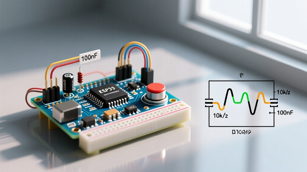
An RC filter smooths out the rapid voltage spikes caused by contact chatter. By placing a 10kΩ resistor in series with the switch and a 100nF (0.1µF) ceramic capacitor in parallel to ground, you create a low-pass filter. The time constant (τ) is calculated as:
τ = R × C
τ = 10,000 Ω × 0.0000001 F = 0.001 seconds (1ms)
While a 1ms time constant absorbs the highest frequency chatter, the resulting voltage curve is exponential, not a sharp digital edge. Microcontroller inputs have specific voltage thresholds (VIL and VIH). A slow-rising exponential curve might linger in the "undefined" logic region, causing the MCU's internal input buffer to oscillate and generate false triggers anyway.
The Schmitt Trigger Solution
To fix the slow edge, we route the RC filter's output through a Schmitt trigger IC, such as the 74HC14 (hex inverting Schmitt trigger), which costs roughly $0.60 per DIP chip in 2026. The Schmitt trigger utilizes hysteresis—meaning it has two distinct voltage thresholds: a higher one for switching LOW-to-HIGH, and a lower one for switching HIGH-to-LOW. This guarantees a razor-sharp, clean digital edge to the Arduino, completely eliminating chatter at the silicon level.
Software Debouncing: Moving Beyond the delay() Crutch
While hardware fixes are electrically superior, they require extra PCB space and components. For 90% of hobbyist and prototyping scenarios, software debouncing is the preferred route. However, the implementation matters immensely.
The Anti-Pattern: Using delay()
Many beginners attempt to solve bounce by inserting delay(50) after reading a button state. While this waits out the 5ms bounce window, it halts the entire microcontroller. If your Arduino is simultaneously driving WS2812B LEDs, reading a rotary encoder, or managing a PID control loop, a 50ms blocking delay will cause catastrophic timing failures. Never use delay() for debouncing in production firmware.
The Professional Approach: State-Change Tracking with millis()
The official Arduino state-change detection documentation outlines a non-blocking method using the millis() timer. By recording the exact millisecond a state change occurs and ignoring any subsequent changes until a predefined window (e.g., 50ms) has passed, the MCU remains free to execute other tasks. While effective, writing this state-machine logic from scratch for multiple buttons quickly bloats your codebase.
Implementing the Bounce2 Library
The industry standard for Arduino button debounce in the maker community is the Bounce2 library repository. It handles the millis() math, edge detection, and state tracking in a highly optimized C++ class. Here is how you implement it for a pin using internal pull-ups:
#include <Bounce2.h>

// Instantiate a Bounce object
Bounce debouncer = Bounce();

void setup() {
  // Configure pin 2 with internal pull-up
  pinMode(2, INPUT_PULLUP);

  // Attach the pin to the debouncer and set 10ms interval
  debouncer.attach(2);
  debouncer.interval(10);
}

void loop() {
  // Update the debouncer state machine
  debouncer.update();

  // Trigger only on the exact moment of a clean falling edge
  if (debouncer.fell()) {
    // Execute button press action safely
    Serial.println("Clean Button Press Registered");
  }
}
Hardware vs. Software: Decision Matrix
Choosing between hardware and software debouncing depends on your project's constraints. Use this matrix to guide your architectural decisions:
| Feature | Hardware (RC + Schmitt) | Software (Bounce2 / millis) |
|---|---|---|
| Bill of Materials (BOM) Cost | +$0.15 per button (R, C, IC share) | $0.00 (Firmware only) |
| CPU Overhead | Zero (Handled in analog domain) | Low (Requires loop polling) |
| Interrupt Compatibility | Excellent (Clean edges prevent ISR flooding) | Poor (Bounce can still trigger multiple ISRs) |
| PCB Space Required | Moderate (Requires routing) | None |
| Best Use Case | Safety limits, industrial CNC, wake-from-sleep | UI menus, media controls, standard prototyping |
Edge Cases: EMI, Long Wires, and 2026 Design Standards
A common failure mode in advanced MCU designs involves Electromagnetic Interference (EMI). If you are wiring a pushbutton located 3 meters away from the Arduino—such as a foot pedal for a welding rig or an outdoor gate sensor—the wire acts as an antenna. Radio frequency interference (RFI) from nearby motors or Wi-Fi routers can induce voltage spikes on the wire that perfectly mimic switch bounces.
Software debouncing cannot reliably distinguish between a 5ms mechanical bounce and a 5ms EMI spike. In these high-noise environments, you must use hardware debouncing. Place the 10kΩ/100nF RC filter physically on the PCB directly adjacent to the microcontroller pin, not at the switch end. Furthermore, use twisted-pair cabling for the remote switch to cancel out induced magnetic fields, and ensure your Arduino ground plane is properly isolated from high-current switching loads.
Finally, if you are utilizing the ESP32's capacitive touch pins instead of mechanical buttons, traditional debounce logic still applies. Environmental humidity and water droplets can cause capacitance flutter. In these scenarios, increasing the software debounce interval to 100ms and requiring a sustained "hold" state via the Bounce2 duration() method will prevent phantom triggers caused by environmental noise.