
The Strain Gauge Arduino Bottleneck
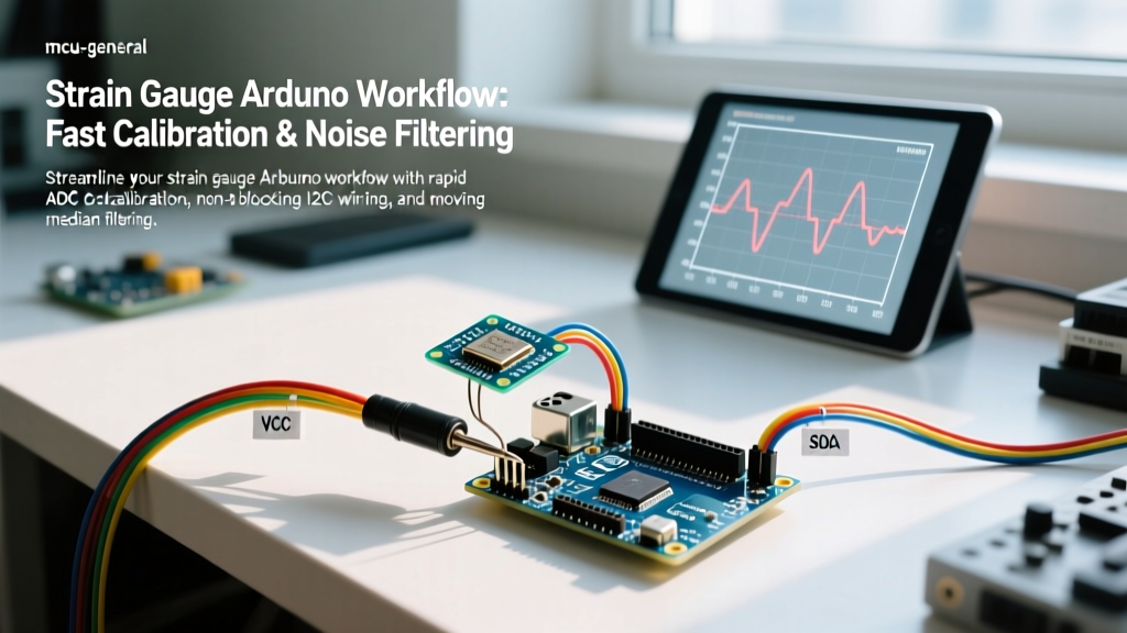
In the 2026 maker and prosumer landscape, integrating a strain gauge Arduino system into a reliable measurement workflow remains a notorious bottleneck. Most online tutorials stop at blinking an LED when a load cell detects weight. However, when you transition from a breadboard prototype to a deployed system—whether for automated dosing, structural health monitoring, or robotics—you immediately encounter three workflow killers: blocking ADC reads, tedious manual calibration, and impulse noise from nearby electromechanical components.
Optimizing your workflow requires abandoning the "copy-paste" hobbyist approach and adopting an engineered pipeline. This guide details a streamlined, production-ready workflow for strain gauge integration, focusing on hardware selection, non-blocking I2C architectures, automated EEPROM calibration, and algorithmic noise rejection.
Phase 1: Upgrading the ADC Architecture
The standard HX711 module has been the default choice for Arduino load cell projects for a decade. While cheap, its proprietary serial protocol requires the microcontroller to wait (block) for the Data Ready pin to pulse. On an ESP32 or Arduino Nano ESP32 running FreeRTOS, a blocking shiftIn() function can starve other tasks, causing network timeouts or motor control jitter.
To optimize your workflow, we recommend migrating to I2C-based ADCs like the NAU7802. Below is a comparison matrix to help you select the right silicon for your pipeline.
| ADC Module | Interface | Blocking Code? | Resolution | 2026 Est. Price | Workflow Rating |
|---|---|---|---|---|---|
| HX711 (Generic) | Proprietary Serial | Yes (High) | 24-bit | $1.50 - $3.00 | ⭐⭐ |
| SparkFun Qwiic Scale (NAU7802) | I2C (Non-Blocking) | No | 24-bit | $11.50 - $14.00 | ⭐⭐⭐⭐⭐ |
| ADS1232 (TI) | Proprietary Serial | Yes (Medium) | 24-bit | $6.00 - $9.00 | ⭐⭐⭐ |
| ADS1115 (16-bit) | I2C | No | 16-bit | $4.00 - $7.00 | ⭐⭐ (Insufficient Res) |
Workflow Pro-Tip: The SparkFun Qwiic Scale (NAU7802) allows you to configure the I2C bus to trigger an interrupt when data is ready. This completely frees your Arduino's main loop to handle PID control or web server tasks while the ADC samples in the background.
Phase 2: Wiring and Thermal Compensation
A major source of workflow delay is debugging "drifting" values after the system has been running for 30 minutes. This is almost always a thermal issue, not a code issue.
The Kelvin Connection and Wheatstone Bridges
According to Omega Engineering's strain gauge guidelines, lead wire resistance can introduce massive errors in quarter-bridge configurations. If you are using discrete strain gauges rather than a pre-packaged full-bridge load cell, you must use a 3-wire or 4-wire (Kelvin) connection to compensate for temperature-induced resistance changes in the copper leads.
- Quarter-Bridge: Requires a dummy gauge on the same material to cancel thermal expansion. High calibration overhead.
- Half-Bridge: Two active gauges. Good for bending beam applications. Moderate thermal compensation.
- Full-Bridge: Four active gauges (e.g., standard S-type or single-point load cells). Inherently temperature-compensated. Always choose full-bridge load cells to eliminate weeks of thermal drift debugging.
Phase 3: The 5-Minute EEPROM Calibration Routine
Manually copying serial monitor output into your sketch's #define statements is a fragile workflow. If you swap the Arduino or the load cell, you must recompile. Instead, implement a 2-point calibration routine that stores the math in the microcontroller's EEPROM.
The physics of a strain gauge amplifier are linear: Weight = (Raw_ADC - Offset) * Scale_Factor.
- Tare (Zero Point): With no load, average 50 raw ADC samples. Store this as
Offset. - Span (Known Load): Place a certified calibration weight (e.g., 10.000 kg) on the cell. Average 50 samples to get
Raw_Loaded. - Calculate:
Scale_Factor = Known_Weight / (Raw_Loaded - Offset). - Commit to EEPROM: Use
EEPROM.put()to save the float values.
#include <EEPROM.h>

struct CalibrationData {
  float offset;
  float scale;
  bool isCalibrated;
};

void saveCalibration(float off, float sc) {
  CalibrationData data = {off, sc, true};
  EEPROM.put(0, data);
  Serial.println("Calibration saved to EEPROM.");
}
By wrapping this in a simple serial command parser, field technicians can recalibrate your strain gauge Arduino device in the field using a laptop, without ever needing the Arduino IDE or a USB programmer.
Phase 4: Algorithmic Noise Rejection
Strain gauges are essentially high-gain antennas for electromagnetic interference (EMI). If your Arduino shares a chassis with stepper motors, solenoid valves, or switching power supplies, you will see massive impulse spikes in your data.
Why the Moving Average Fails
The standard workflow relies on a Moving Average filter. The problem? If a relay clicks and induces a 5,000-count spike on a 24-bit ADC, a 10-sample moving average will "smear" that spike across the next 10 readings, corrupting your data for several seconds.
The Moving Median Solution
Instead, implement a Moving Median Filter. By taking 5 samples, sorting them, and selecting the middle value, you completely reject impulse noise without smearing it. As noted in Analog Devices' guide to instrumentation amplifiers, digital post-filtering is a necessary secondary defense when hardware shielding cannot eliminate all coupled noise.
int32_t samples[5];

int32_t getMedianReading() {
  for(int i=0; i<5; i++) {
    samples[i] = readADC(); // Your non-blocking I2C read function
    delayMicroseconds(50);  // Allow ADC settling
  }
  // Simple bubble sort for 5 elements
  for(int i=0; i<4; i++) {
    for(int j=0; j<4-i; j++) {
      if(samples[j] > samples[j+1]) {
        int32_t temp = samples[j];
        samples[j] = samples[j+1];
        samples[j+1] = temp;
      }
    }
  }
  return samples[2]; // Return the median (middle) value
}
Phase 5: Edge Cases and Deployment Realities
Even with optimized code and I2C hardware, real-world deployments introduce mechanical edge cases that ruin data integrity. Build these checks into your startup workflow:
- Creep Compensation: Strain gauge adhesives and the metal substrate itself exhibit "creep" under sustained load. If your Arduino monitors a static load for hours, expect a 0.05% to 0.1% drift. Implement a software "deadband" that ignores micro-changes if the derivative of the weight over time is near zero.
- ADC Saturation Check: Always check the ADC status registers. If the NAU7802 or HX711 returns exactly
8388607(0x7FFFFF) or-8388608, the amplifier is saturated. Your mechanical linkage is binding, or the load cell is overloaded. Flag this as a hardware fault rather than outputting a false weight. - Ground Loops: Never connect the shield of a load cell cable to the Arduino ground at both ends. Connect it at the ADC end only to prevent 50Hz/60Hz mains hum from traversing your Wheatstone bridge.
Conclusion: Time Saved is Precision Gained
Transitioning your strain gauge Arduino workflow from a hobbyist paradigm to an engineered pipeline requires upfront effort, but the ROI is massive. By upgrading to an I2C NAU7802, you eliminate RTOS blocking. By implementing EEPROM-based 2-point calibration, you eliminate hard-coded recompilation. Finally, by swapping moving averages for moving median filters, you immunize your system against the EMI reality of modern maker spaces. Adopt these protocols, and your next load cell deployment will be robust, repeatable, and ready for production.