
Building a Custom Flight Controller with Arduino: The Ultimate FAQ
Designing and coding your own flight controller with Arduino is one of the most rewarding projects in the maker community. Unlike plug-and-play commercial options like Pixhawk or Betaflight-based stacks, a DIY approach forces you to understand the underlying physics, sensor fusion mathematics, and real-time control loops. However, bridging the gap between a blinking LED and a stable quadcopter involves navigating complex hardware constraints and firmware edge cases.
This quick reference guide and FAQ addresses the most critical technical hurdles you will face when building a custom flight controller with Arduino, from IMU selection and I2C bus management to ESC protocols and vibration isolation.
Quick Reference: Hardware Bill of Materials (BOM)
Before diving into the code, ensure your hardware stack is capable of handling real-time kinematic calculations. Below is a recommended baseline BOM for a custom Arduino-based quadcopter build in 2026.
| Component | Recommended Model | Approx. Cost | Role & Notes |
|---|---|---|---|
| Microcontroller | Teensy 4.1 or Arduino Nano 33 IoT | $28 - $32 | Teensy offers 600MHz ARM Cortex-M7 for heavy math; Nano 33 IoT has an onboard LSM6DS3 IMU. |
| IMU (Inertial Measurement Unit) | Bosch BNO055 or InvenSense MPU-6050 | $15 - $22 | BNO055 features onboard sensor fusion (quaternions). MPU-6050 is cheaper but requires heavy CPU math. |
| Barometer | BMP280 or BMP388 | $4 - $8 | Provides altitude hold. BMP388 offers lower noise and higher sampling rates. |
| Power Supply (BEC) | Hobbywing 5V/3A UBEC | $9 - $12 | Steps down LiPo voltage (12V-16V) to a clean 5V rail for the MCU and sensors. |
| ESCs (Electronic Speed Controllers) | BLHeli_S 30A (Opto-isolated) | $18 each | Supports OneShot125 and DShot protocols for lower latency than standard 50Hz PWM. |
Core Hardware FAQs
Which Arduino board is actually viable for a flight controller?
The classic Arduino Uno (ATmega328P, 16MHz) is excellent for learning basic PID theory on a single-axis test rig, but it is not recommended for a fully functional multirotor. The 16MHz clock speed and 2KB SRAM bottleneck sensor fusion algorithms (like Madgwick or Mahony filters) and limit your control loop to roughly 100Hz-150Hz, which results in sluggish flight dynamics.
For a viable custom flight controller with Arduino IDE support, step up to:
- Teensy 4.1 (ARM Cortex-M7, 600MHz): The undisputed king of Arduino-compatible DIY flight controllers. It can run 1000Hz+ PID loops, handle floating-point math natively, and manage multiple hardware UARTs for GPS and telemetry.
- Arduino Nano 33 IoT (ARM Cortex-M0+, 48MHz): A great middle-ground. It includes an onboard LSM6DS3 IMU, eliminating I2C wiring complexity, and has enough processing power for a stable 250Hz control loop.
- Arduino Mega 2560: Useful if you need extensive UART ports for telemetry, GPS, and optical flow sensors, though its 16MHz clock still requires offloading sensor fusion to a smart IMU like the BNO055.
IMU Selection: Should I use the MPU-6050 or BNO055?
This is the most common crossroads for DIY builders. The MPU-6050 (often found on $2 GY-521 breakout boards) outputs raw accelerometer and gyroscope data. Your Arduino must calculate the sensor fusion (combining the fast-drifting gyro with the noisy but gravity-referenced accelerometer) using a complementary or Kalman filter. On an 8-bit AVR, this math eats up precious CPU cycles.
The Bosch BNO055 (approximately $18 on Adafruit or generic breakouts) contains an internal Cortex-M0 processor that handles sensor fusion natively, outputting clean, drift-free quaternions via I2C. According to the Adafruit BNO055 Overview, this offloads the heavy math from your main Arduino, allowing you to focus entirely on the PID control loop and motor mixing. For beginners building a flight controller with Arduino, the BNO055 is highly recommended to bypass firmware math bottlenecks.
Wiring & Communication Quick Reference
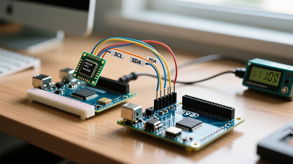
How do I prevent I2C bus lockups and noisy sensor data?
I2C is notoriously sensitive to electrical noise generated by brushless motors and ESCs. A common failure mode is the Arduino hanging indefinitely on a Wire.requestFrom() command due to a corrupted I2C bus state.
Critical Wiring Rule: Always use 4.7kΩ pull-up resistors on the SDA and SCL lines if your breakout boards do not have them built-in. Furthermore, keep I2C traces under 10cm and route them away from ESC power wires.
To maximize data throughput, initialize your I2C bus at 400kHz (Fast Mode) in your setup() function. As detailed in the official Arduino Wire Library Reference, you can achieve this by calling Wire.setClock(400000);. This reduces the time the bus is tied up, allowing for higher PID loop frequencies.
What is the correct pinout for standard ESC PWM?
If you are using the standard Servo.h library, you are limited to 50Hz (a 20ms period with a 1000µs to 2000µs pulse width). Connect your ESC signal wires to any digital PWM-capable pins (e.g., Pins 3, 5, 6, 9 on an Arduino Nano). Never power the Arduino 5V rail directly from the ESC's built-in BEC if you are running high-draw peripherals; use a dedicated UBEC to prevent brownouts during aggressive maneuvers.
Firmware, PID, and Loop Rates
How fast should my PID control loop run?
A stable quadcopter requires a minimum control loop rate of 250Hz (executing the PID math and sending motor commands 250 times per second). High-performance racing drones push this to 1000Hz or higher. If your loop rate fluctuates (jitter), the derivative (D) term in your PID controller will amplify the timing noise, causing violent motor oscillations.
Actionable Fix: Do not use delay() in your flight code. Use a non-blocking timer interrupt or a micros() based loop to guarantee a fixed time step (dt) for your integral and derivative calculations.
Standard PWM vs. OneShot125
Standard 50Hz PWM updates motor speeds every 20 milliseconds. If your PID loop runs at 250Hz (4ms per loop), the ESC is only receiving a new command every 5th loop iteration. This introduces severe latency. OneShot125 shrinks the pulse width to 125µs–250µs, allowing update rates up to 500Hz. Implementing OneShot125 on an Arduino requires bypassing Servo.h and directly manipulating hardware timers (like Timer1 on the ATmega328P) to generate precise microsecond pulses.
Troubleshooting Matrix: Flight Controller Failures
| Symptom | Probable Root Cause | Engineering Solution |
|---|---|---|
| Quadcopter drifts continuously in one direction despite level calibration. | IMU temperature drift or mechanical stress on the solder joints altering the zero-g offset. | Implement a software warm-up routine. Discard the first 3 seconds of IMU data on boot while the sensor reaches thermal equilibrium. |
| Violent, high-frequency motor twitching (desyncs) when applying throttle. | D-term noise in the PID controller amplified by high-frequency frame vibrations. | Apply a Digital Low Pass Filter (DLPF) to the gyro data. If using an MPU-6050, write to register 0x1A to set the DLPF to 44Hz bandwidth. |
| Arduino resets randomly during aggressive flips or high-throttle punches. | Voltage brownout caused by ESC back-EMF or sudden current spikes dropping the 5V rail below 3.3V. | Add a 100µF low-ESR electrolytic capacitor and a 0.1µF ceramic decoupling capacitor directly across the 5V and GND pins on the Arduino. |
| Yaw axis spins out of control (toilet bowling effect). | Magnetometer (compass) interference from high-current battery leads. | Move the magnetometer away from power distribution board (PDB) traces, or rely purely on gyro-integrated yaw (which will drift over time but prevents immediate spin-outs). |
Power Distribution & Vibration Isolation
Why Vibration Isolation is Non-Negotiable
Accelerometers measure all acceleration, including the high-frequency micro-vibrations from 2207 brushless motors spinning at 25,000 RPM. If these vibrations couple into the IMU, the flight controller will interpret them as physical movement and attempt to correct for them, leading to a destructive feedback loop.
According to the ArduPilot vibration mounting guidelines, hard-mounting an IMU directly to a carbon fiber frame almost guarantees poor flight performance. You must decouple the flight controller using:
- 3M VHB 4910 Tape: Provides excellent high-frequency dampening while maintaining enough rigidity to prevent low-frequency pendulum effects.
- O-Ring Suspension: Mounting the Arduino board on four rubber O-rings stretched between standoffs. Ensure the board is floating freely and not touching any rigid headers or wires that could transmit vibrations.
- Software Filtering: Always pair physical isolation with a software biquad or moving-average low-pass filter on the accelerometer data before it enters the PID matrix.
Powering the Brains Safely
Never use a linear voltage regulator (like the L7805) to step down a 3S or 4S LiPo (12.6V - 16.8V) to 5V for your Arduino. The voltage differential dissipated as heat will trigger the regulator's thermal shutdown mid-flight, resulting in an immediate crash. Always use a switching buck converter (UBEC) rated for at least 3A continuous current, ensuring your microcontroller and sensors receive clean, ripple-free power even when the main battery sags under heavy motor loads.