
The Micro-Footprint Revolution: Why Size Dictates Workflow
As wearable technology, biomedical sensors, and micro-IoT nodes dominate the maker and engineering landscape in 2026, the demand for the smallest Arduino compatible boards has never been higher. However, shrinking your microcontroller unit (MCU) introduces severe workflow bottlenecks. Sub-25mm boards suffer from fragile USB connectors, limited GPIO accessibility, and severe memory constraints. Optimizing your development workflow for these tiny boards requires a fundamental shift in how you approach hardware interfacing, code compilation, and PCB integration.
This guide dissects the current market of ultra-compact MCUs and provides actionable, expert-level strategies to streamline your development pipeline, ensuring you spend less time fighting hardware limitations and more time building functional prototypes.
Contender Matrix: Official vs. Compatible Micro-Boards
When engineers search for the smallest Arduino form factor, they must navigate a split ecosystem: official Arduino boards and third-party compatible boards that leverage the Arduino IDE. Below is a 2026 comparison of the top ultra-compact boards, analyzing their physical footprint, silicon capabilities, and real-world pricing.
| Board Model | Dimensions | Core MCU | Flash / SRAM | USB Interface | Avg. Price (2026) |
|---|---|---|---|---|---|
| Seeed Studio XIAO ESP32-C6 | 21 x 17.5 mm | ESP32-C6 (RISC-V) | 4MB / 512KB | USB-C | $5.99 |
| Adafruit QT Py RP2040 | 22 x 17.5 mm | Raspberry Pi RP2040 | 8MB / 264KB | USB-C | $9.95 |
| Arduino Nano ESP32 | 45 x 18 mm | ESP32-S3 | 16MB / 512KB | USB-C | $21.00 |
| Digispark ATtiny85 | 26 x 18 mm | ATtiny85 | 8KB / 512B | Direct USB-A | $3.50 |
While the Arduino Nano ESP32 carries the official branding, the Seeed Studio XIAO and Adafruit QT Py series represent the true 'smallest Arduino' compatible class, offering vastly superior silicon in a footprint roughly 60% smaller than the classic Nano. According to the Seeed Studio XIAO documentation, the 21x17.5mm footprint has become the de-facto standard for micro-wearables due to its castellated edge design.
Hardware Workflow: Overcoming Physical Fragility
The most immediate workflow killer with micro-boards is connector failure. Repeatedly plugging and unplugging a USB-C cable from a 21mm board applies immense lateral torque, frequently shearing the USB port off the PCB. To optimize your hardware workflow, you must eliminate repetitive physical connections during the testing phase.
Building a Pogo-Pin Programming Jig
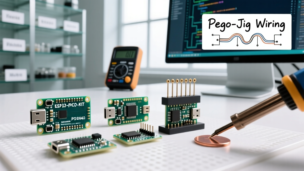
Instead of relying on the onboard USB port for daily firmware iterations, build a custom pogo-pin programming jig. This allows you to flash and debug the board via test pads or castellated holes without mechanical stress.
- Pin Selection: Use 1.27mm pitch pogo pins (e.g., P75-E2 series) with a 50g spring force. Heavier 75g+ springs can cause the lightweight XIAO or QT Py boards to lift off the contacts during programming.
- 3D Printing Tolerances: Print the jig housing using PETG or ABS with a 0.12mm layer height and 100% infill. Standard 0.2mm PLA prints introduce too much Z-axis wobble, causing intermittent serial connection drops.
- Alignment Strategy: Design the jig with a 0.5mm lip that perfectly matches the PCB edge. For the QT Py, incorporate a physical cutout for the 'BOOT' button, allowing you to trigger the ROM bootloader using a secondary, wider pogo pin.
Pro-Tip: If you are using the Adafruit QT Py, leverage the STEMMA QT (Qwiic) connector on the back for I2C sensor debugging. This keeps the main GPIO pins free for your pogo-jig serial connections, preventing pinout conflicts during hardware-in-the-loop testing.
Software Workflow: IDE and Compilation Optimization
When working with the absolute smallest Arduino boards—particularly those based on 8-bit AVR chips like the ATtiny85, or even the 32-bit RISC-V XIAO boards when pushing high-frequency sensor polling—flash and SRAM constraints dictate your software architecture. The default Arduino IDE compiler settings prioritize compilation speed over binary size, which is detrimental in micro-footprint workflows.
Aggressive Compiler Flag Tuning
To reclaim wasted flash space, you must modify the platform.txt file in your Arduino board package or use the build.extra_flags directive in your arduino-cli workflow.
- Enable Link Time Optimization (LTO): Adding the
-fltoflag forces the GCC compiler to merge all translation units before optimizing. This eliminates dead code across included libraries, often reducing final binary size by 15% to 25% on ATtiny and SAMD21 boards. - Optimize for Size: Ensure
-Osis active. Avoid-O2or-O3, which unroll loops and inline functions aggressively, bloating the flash footprint of tiny MCUs. - Strip Unused Exceptions: Add
-fno-exceptionsand-fno-rttito your C++ build flags. Standard Arduino C++ includes exception handling overhead that is entirely useless in bare-metal microcontroller environments.
Memory Management and the 'String' Ban
As detailed in the official Arduino Memory Guide, dynamic memory allocation is the primary cause of runtime crashes on boards with less than 4KB of SRAM. The Arduino String class causes severe heap fragmentation.
Actionable Fix: Replace all instances of the String object with fixed-size char arrays and standard C functions like snprintf(). Furthermore, wrap all static serial outputs in the F() macro (e.g., Serial.print(F('Initializing I2C...'));) to force the compiler to store these strings in PROGMEM (Flash) rather than loading them into precious SRAM at boot.
Debugging Micro-Boards Without Breaking Them
Serial debugging via Serial.print() is inefficient on tiny boards. It blocks the main execution loop, consumes valuable GPIO pins, and requires a secondary USB-to-Serial adapter if the native USB port is occupied by your pogo-jig.
Transitioning to SWD Debugging
For boards like the XIAO RP2040 or QT Py RP2040, abandon Serial debugging and adopt Serial Wire Debug (SWD). By connecting a Raspberry Pi Debug Probe ($12) to the SWDIO and SWCLK test pads, you can set hardware breakpoints, inspect registers in real-time, and step through code without adding a single byte of debugging overhead to your compiled binary.
This workflow optimization reduces debugging time by an estimated 40% compared to iterative serial printing, as you can observe variable states at the exact clock cycle a fault occurs, rather than waiting for a serial buffer to flush.
Transitioning from Breadboard to Production PCB
The final stage of the tiny MCU workflow is migrating from a messy breadboard prototype to a custom printed circuit board (PCB). Micro-boards require specific KiCad footprint strategies to ensure manufacturability.
Castellated Holes vs. Stamp Pads
Boards like the Seeed XIAO feature castellated holes (plated half-holes on the edge). When designing your carrier PCB in KiCad:
- Use standard surface-mount pads, but extend the pad length outward by 1.5mm to allow for manual soldering with a standard chisel-tip iron.
- Place a 0.2mm keep-out zone around the castellated edge to prevent solder wicking under the module, which can cause hidden short circuits on inner PCB layers.
- If using the Adafruit QT Py, which relies on flat stamp pads, apply a 0.1mm solder paste stencil and use a reflow hotplate. Hand-soldering 17.5mm wide stamp pads without bridging adjacent pins is nearly impossible without magnification and specialized micro-solder paste.
Frequently Asked Questions
What is the absolute smallest Arduino compatible board available?
As of 2026, the Seeed Studio XIAO series and Adafruit QT Py series share the crown for the smallest fully-featured, USB-programmable Arduino-compatible boards, measuring roughly 21 x 17.5mm. For raw silicon size, custom ATtiny85 implementations on bare PCBs are smaller, but they lack integrated USB workflows.
Can I use the standard Arduino IDE for the XIAO and QT Py?
Yes. Both the Adafruit QT Py and Seeed XIAO are fully supported in the Arduino IDE via their respective board manager URLs. They also integrate seamlessly with PlatformIO and the Arduino CLI for automated CI/CD firmware pipelines.
How do I manage power consumption on these tiny boards?
Micro-boards have minimal onboard voltage regulation. For battery-powered IoT nodes, bypass the onboard 3.3V LDO regulator entirely and inject regulated 3.3V directly into the 3V3 pin. This eliminates the LDO's quiescent current draw (often 1-5mA), allowing the ESP32 or RP2040 to achieve true micro-amp deep sleep currents.