
The HC-SR04 in 2026: Beyond the Basic Tutorial
Despite the proliferation of Time-of-Flight (ToF) and solid-state LiDAR sensors, the Arduino HC-SR04 remains a ubiquitous staple in prototyping and education. Retailing between $1.50 and $3.50, this 40kHz ultrasonic transceiver offers a cost-effective 2cm to 400cm ranging capability. However, the vast majority of online guides fail to address the physical and electrical edge cases that cause jitter, phantom readings, and microcontroller lockups.
This configuration guide bypasses the rudimentary "blink-and-ping" tutorials. We will cover precise voltage division for 3.3V logic boards (like the ESP32 and Raspberry Pi Pico), interrupt-driven library configuration, and the thermodynamic calibration required for millimeter-level accuracy.
Hardware Anatomy and Pinout Configuration
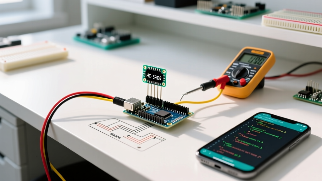
The HC-SR04 relies on a pair of 40kHz aluminum mesh transducers and an onboard comparator circuit (often an LM324 or equivalent op-amp network) to process the acoustic echo. Understanding the electrical characteristics of these pins is critical for stable operation.
| Pin | Function | Electrical Characteristics | Configuration Notes |
|---|---|---|---|
| VCC | Power Supply | 5.0V DC (Draws ~15mA during ping, ~2mA idle) | Must be a stable 5V. Do not power from the Arduino 5V pin if using high-draw servos simultaneously. |
| TRIG | Trigger Input | 5V TTL Logic (Accepts 3.3V reliably) | Requires a minimum 10µs HIGH pulse to initiate the 8-cycle burst. |
| ECHO | Echo Output | 5V TTL Logic Output | Outputs 5V HIGH for the duration of the flight time. Requires stepping down for 3.3V MCUs. |
| GND | Ground | Common Ground | Must share a common ground plane with the MCU to prevent floating logic states. |
Wiring for 3.3V Microcontrollers (ESP32, RP2040, Teensy)
A frequent failure mode in modern maker projects is connecting the HC-SR04 ECHO pin directly to a 3.3V microcontroller GPIO. Because the sensor is powered by 5V, the ECHO pin outputs a 5V HIGH signal. Feeding 5V into an ESP32 or Raspberry Pi Pico GPIO will degrade the silicon over time or cause immediate catastrophic failure.
The Voltage Divider Solution
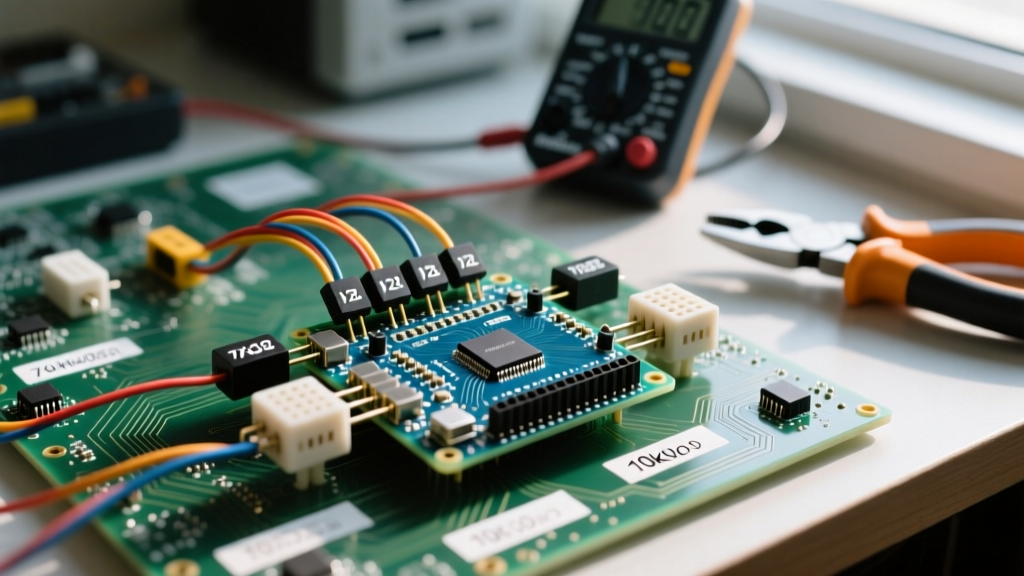
To safely interface the 5V ECHO signal with a 3.3V logic input, you must configure a resistive voltage divider. According to standard voltage divider principles, we need to drop 5V down to a safe ~3.3V.
- R1 (Series Resistor): 1kΩ (Connected between HC-SR04 ECHO and MCU GPIO)
- R2 (Pull-down Resistor): 2kΩ (Connected between MCU GPIO and GND)
Calculation: V_out = 5V × (2000 / (1000 + 2000)) = 3.33V. This is perfectly within the 3.6V absolute maximum rating of modern 3.3V logic gates.
Pro-Tip for 5V Boards (Arduino Uno/Mega): If you are using a standard 5V ATmega328P or ATmega2560 board, you can wire the ECHO pin directly to the digital input. No voltage division is required.
Software Configuration: Ditching pulseIn() for NewPing
The standard Arduino pulseIn() function is fundamentally flawed for ultrasonic ranging. It is a blocking function; if the sensor fails to receive an echo (due to acoustic absorption or out-of-bounds targeting), pulseIn() will halt your entire sketch for up to 1 second (the default timeout), causing catastrophic latency in motor control or UI loops.
Instead, professional configurations utilize the NewPing library, which leverages hardware timer interrupts to measure the echo pulse asynchronously.
Optimal IDE Code Implementation
Install the NewPing library via the Arduino Library Manager. Below is the optimized configuration for non-blocking, high-speed polling.
#include <NewPing.h>

// Pin Configuration
#define TRIGGER_PIN  9
#define ECHO_PIN     10
#define MAX_DISTANCE 400 // Maximum distance we want to ping (in cm)

// Initialize NewPing object
NewPing sonar(TRIGGER_PIN, ECHO_PIN, MAX_DISTANCE);

void setup() {
  Serial.begin(115200);
  // NewPing handles pinmodes internally, no need for pinMode()
}

void loop() {
  // Wait 50ms between pings (29ms is the absolute minimum to avoid echo overlap)
  delay(50);

  // ping() returns the raw time in microseconds (uS)
  unsigned int uS = sonar.ping();

  // Convert uS to cm using the library's built-in constant
  unsigned int cm = uS / US_ROUNDTRIP_CM;

  Serial.print("Distance: ");
  Serial.print(cm);
  Serial.println(" cm");
}
Thermodynamic Calibration for Precision Ranging
Most basic sketches hardcode the speed of sound to 343 meters per second. However, the speed of sound in dry air is highly dependent on ambient temperature. According to Georgia State University's HyperPhysics database, the speed of sound increases by approximately 0.6 m/s for every 1°C rise in temperature.
If your project operates in an unheated garage at 5°C, the speed of sound drops to ~334 m/s. Using the standard 343 m/s constant will introduce a 2.7% measurement error—translating to a 2.7cm drift over a 1-meter distance.
Implementing Temperature Compensation
To achieve millimeter-level accuracy, integrate a digital temperature sensor (like a BME280 or DS18B20) and apply the following compensation formula in your sketch:
float getCompensatedDistance(unsigned int uS, float tempC) {
  // Calculate actual speed of sound in cm/uS based on temperature
  // v = 331.4 + (0.6 * T) in m/s
  float speedOfSound_ms = 331.4 + (0.6 * tempC);
  float speedOfSound_cm_uS = speedOfSound_ms / 10000.0;

  // Distance = (Time / 2) * Speed
  float distance_cm = (uS / 2.0) * speedOfSound_cm_uS;
  return distance_cm;
}
Troubleshooting Matrix: Edge Cases and Failure Modes
Ultrasonic sensors interact with the physical world in unpredictable ways. Use this diagnostic matrix to resolve common HC-SR04 anomalies.
| Symptom | Physical / Electrical Cause | Configuration Fix |
|---|---|---|
| Constant 0cm Readings | Target is inside the 2cm blind spot, or transducer mesh is physically crushed/dented, altering the 40kHz resonance. | Ensure target is >3cm away. Inspect transducer mesh for physical damage. Replace sensor if dented. |
| Constant MAX_DISTANCE (e.g., 400cm) | Acoustic absorption (target is foam/fabric) or specular reflection (target is angled glass/metal, deflecting the beam away). | Add a piece of matte cardboard to the target surface to diffuse the acoustic wave back to the receiver. |
| Random Massive Spikes (e.g., jumping from 20cm to 350cm) | Cross-talk from another 40kHz sensor nearby, or electrical noise on the 5V rail triggering the comparator falsely. | Stagger sensor firing times by at least 35ms. Add a 100µF decoupling capacitor across the sensor's VCC and GND pins. |
| Sketch Freezes / Locks Up | Using standard pulseIn() without a timeout, or ECHO pin floating due to a broken jumper wire. |
Switch to NewPing library. Verify continuity of ECHO wire. Ensure pull-down resistor is present if using a breadboard. |
Acoustic Beam Profiling and Placement
The HC-SR04 does not emit a laser-like beam; it projects a 15-degree conical acoustic wave. At a distance of 100cm, the "footprint" of the ultrasonic burst is roughly 26cm in diameter.
When configuring your sensor for robotics or tank-level monitoring, you must account for this beam width. If the sensor is mounted too close to the edge of a chassis, the outer edge of the acoustic cone will strike the chassis itself, returning a false "obstacle detected" reading. Rule of thumb: Mount the HC-SR04 at least 15cm inward from any lateral structural obstructions, or 3D print an acoustic shroud lined with open-cell foam to dampen the peripheral wave propagation.
Summary
Configuring the Arduino HC-SR04 for reliable, production-grade performance requires moving beyond basic wiring diagrams. By implementing 3.3V voltage dividers, migrating to interrupt-driven libraries like NewPing, and applying thermodynamic compensation, you can extract highly accurate, jitter-free data from this remarkably economical sensor. Whether you are building an autonomous rover or a DIY parking assistant, respecting the acoustic and electrical physics of the 40kHz transducers is the key to success.