
The PWM Illusion: Why Standard Boards Fall Short
When engineers and makers search for an arduino output analog solution, they frequently encounter a fundamental hardware misunderstanding. The classic Arduino Uno (ATmega328P) and Nano do not possess true Digital-to-Analog Converters (DACs). Instead, the analogWrite() function generates Pulse Width Modulation (PWM). While PWM is excellent for dimming LEDs or controlling DC motor speed via inertia, it is a digital square wave, not a continuous analog voltage.
According to the official Arduino analogWrite() reference, the ATmega328P outputs an 8-bit PWM signal (0-255) at a base frequency of 490 Hz, with pins 5 and 6 operating at 980 Hz. If you feed this raw PWM signal into a high-impedance audio amplifier or a precision scientific sensor, you will introduce severe high-frequency noise, ripple, and quantization errors. To achieve a true, continuous DC voltage or high-fidelity audio waveform, you must utilize microcontrollers with native DAC peripherals or integrate external DAC integrated circuits (ICs).
Native True Arduino Output Analog: Board Compatibility Matrix
If your project demands low-latency, native analog output without the overhead of I2C or SPI communication, selecting the right development board is critical. Below is a compatibility matrix of popular maker boards featuring true hardware DACs, updated for the current 2026 hardware landscape.
| Microcontroller Board | Core Architecture | DAC Resolution | Max Sample Rate | Native Analog Pins |
|---|---|---|---|---|
| Arduino Uno R4 Minima | Renesas RA4M1 (Cortex-M4) | 12-bit (0-4095) | ~100 ksps | A0 (DAC) |
| Arduino Due | Atmel SAM3X8E (Cortex-M3) | 12-bit (0-4095) | 350 ksps | DAC0, DAC1 |
| Teensy 4.1 | NXP i.MX RT1062 (Cortex-M7) | 12-bit (via MQS/PWM) | High (Audio Lib) | A21, A22 (True DAC) |
| ESP32-S3 DevKit | Xtensa LX7 (Dual-Core) | No native DAC* | N/A | N/A (Use PWM/I2S) |
*Note: The original ESP32 featured a rudimentary 8-bit DAC on GPIO25/26, but the widely adopted ESP32-S3 and ESP32-C3 variants removed this peripheral. For ESP32 analog output, external I2S or I2C DACs are mandatory.
External DAC Integration: I2C vs SPI Architectures
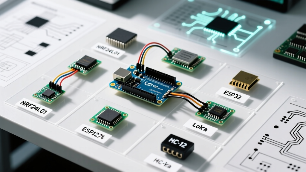
When native DACs are unavailable or insufficient for your resolution requirements, external DAC ICs provide a robust arduino output analog pathway. The choice between I2C and SPI protocols dictates your wiring complexity, update rates, and pin consumption.
The I2C Standard: Microchip MCP4725
The MCP4725 is the undisputed workhorse of maker-space I2C DACs. It offers 12-bit resolution and operates from 2.7V to 5.5V. Breakout boards typically cost between $3.50 and $5.00. As detailed in the Microchip MCP4725 product documentation, the device features an onboard EEPROM to remember the last set voltage across power cycles.
Critical EEPROM Warning: The MCP4725 allows you to write to both the volatile DAC register and the non-volatile EEPROM simultaneously. Never use the EEPROM write command inside a continuous loop(). The EEPROM is rated for only 10,000 write cycles. Updating it at 100 Hz will destroy the memory sector in under two minutes. Always use volatile-only writes for dynamic waveforms.
The SPI Alternative: Analog Devices AD5683R
For precision instrumentation requiring 16-bit resolution (65,536 discrete steps), SPI-based DACs like the AD5683R are necessary. Priced around $11.00 to $14.00 per IC, it offers a settling time of 5 µs and an integrated precision reference. SPI requires more pins (MOSI, SCK, CS, LDAC) but bypasses the 400 kHz / 1 MHz clock limits of I2C, allowing for significantly faster analog update rates required in PID control loops.
Signal Conditioning: Buffering and Filtering
Generating the digital representation of an analog signal is only half the battle. The physical output stage requires careful signal conditioning to interface with real-world loads.
The Rail-to-Rail Op-Amp Trap
A common failure mode occurs when makers attempt to buffer a 0-5V DAC output using the ubiquitous LM358 operational amplifier. The LM358 is not a rail-to-rail output device. On a single 5V supply, its output will saturate around 3.5V, completely ruining your upper analog range. The Solution: Use a true rail-to-rail I/O (RRIO) op-amp like the Microchip MCP6002 (approx. $0.80) or the Texas Instruments OPA333. These will swing within millivolts of your supply rails, preserving the full 0-5V dynamic range.
PWM Low-Pass RC Filtering
If you are forced to use PWM as an analog source (e.g., on an ATmega328P), you must filter the square wave into a DC voltage using a passive RC low-pass filter. The cutoff frequency ($f_c$) is calculated as:
f_c = 1 / (2 * π * R * C)
For a standard 490 Hz PWM signal, a resistor of 10 kΩ and a capacitor of 100 nF yields a cutoff frequency of ~159 Hz. This adequately smooths the 490 Hz carrier but limits your analog signal bandwidth to roughly 15 Hz. If you need faster analog response times, you must increase the PWM frequency via hardware timer registers (e.g., pushing Timer1 to 31.25 kHz) and adjust the RC values accordingly.
Step-by-Step: Deploying the MCP4725 for 0-10V Industrial Control
Industrial PLCs and variable frequency drives (VFDs) often require a 0-10V analog input for speed or torque control. Since the MCP4725 outputs a maximum of 5V (when VDD=5V), you must apply a non-inverting gain stage.
- Voltage Reference: Power the MCP4725 with a clean, regulated 5V supply. Any noise on VDD directly translates to noise on your analog output.
- I2C Pull-ups: Ensure 4.7 kΩ pull-up resistors are present on the SDA and SCL lines. Many cheap breakout boards omit these, leading to I2C bus lockups in electrically noisy industrial panels.
- Gain Stage: Configure an MCP6002 op-amp in a non-inverting configuration with a gain of 2.0. Use precision 1% resistors: $R_f = 10 kΩ$ and $R_i = 10 kΩ$.
- Power Supply: The op-amp must be powered by at least 12V (e.g., a standard 12V or 15V rail) to ensure it can swing fully to 10V without clipping at the top rail.
For a comprehensive wiring schematic and code library implementation, the Adafruit MCP4725 Learning Guide provides excellent baseline C++ examples that can be adapted for industrial gain staging.
Edge Cases and Troubleshooting
Ground Loop Interference
When connecting your Arduino's analog output to a separately powered device (like a mains-powered audio mixer or motor driver), differences in ground potential will inject 50/60 Hz hum into your signal. Always use an audio isolation transformer for AC-coupled signals, or an isolated DC-DC converter paired with an ISO124 isolation amplifier for DC-coupled precision signals.
Quantization Noise in Audio Applications
A 12-bit DAC provides 72 dB of theoretical dynamic range. While sufficient for basic function generators or control voltages (CV) in modular synthesizers, it falls short of CD-quality audio (16-bit / 96 dB). For high-fidelity audio arduino output analog projects, bypass standard microcontroller DACs entirely and route I2S digital audio streams to a dedicated audio DAC like the PCM5102A.