
The Core Challenge: Why Simple Button Reads Fail
Wiring an Arduino LED with push button control is universally recognized as the 'Hello World' of physical computing. However, most beginners quickly encounter a frustrating reality: the LED flickers unpredictably, triggers multiple times from a single press, or fails to register entirely. This is rarely a code logic error; it is a fundamental misunderstanding of mechanical switch physics and floating GPIO pins.
In this comprehensive 2026 guide, we move beyond the flawed delay() based tutorials. We will engineer a robust, non-blocking, edge-triggered circuit using internal pull-up resistors and software debouncing. Whether you are using the classic ATmega328P-based Uno R3 or the modern Renesas RA4M1-powered Uno R4 Minima, the principles of signal integrity remain identical.
Bill of Materials (BOM) and 2026 Component Pricing
To build a reliable interface, component selection matters. Cheap, unbranded tactile switches often suffer from severe contact oxidation and excessive bounce times. We recommend spec-grade components for permanent installations or professional prototypes.
| Component | Specific Model / Value | Estimated Cost (2026) | Engineering Notes |
|---|---|---|---|
| Microcontroller | Arduino Uno R4 Minima | $20.00 | Features a 12-bit ADC and Renesas RA4M1 ARM Cortex-M4 processor. |
| Tactile Switch | Omron B3F-1000 (SPST-NO) | $0.35 | Gold-plated contacts, 100,000 cycle lifespan, ~5ms bounce time. |
| LED | Kingbright WP710A10LSURCK (Red) | $0.15 | Forward Voltage (Vf): 2.0V, Forward Current (If): 20mA. |
| Current Limiter | 220Ω Carbon Film Resistor (1/4W) | $0.02 | Restricts current to ~13.6mA, safely below the 20mA GPIO limit. |
| Prototyping | 400-point Solderless Breadboard | $6.50 | Ensure tight internal spring clips to avoid intermittent connections. |
Hardware Wiring: Eliminating External Resistors
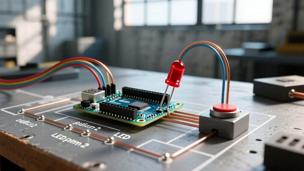
Historically, tutorials required a 10kΩ external pull-up or pull-down resistor to prevent 'floating' pin states when the button was unpressed. Modern Arduino architectures include built-in 20kΩ to 50kΩ internal pull-up resistors, activated via software. This simplifies the Arduino LED with push button wiring to just four physical connections.
Step-by-Step Wiring Guide
- LED Anode (Long Leg): Connect to Digital Pin 8 via the 220Ω current-limiting resistor. (Never connect an LED directly to a GPIO pin; the resulting current spike will permanently degrade the silicon trace).
- LED Cathode (Short Leg): Connect directly to the GND rail on the breadboard.
- Push Button Pin 1: Connect to Digital Pin 2.
- Push Button Pin 2: Connect to the GND rail (shared with the LED cathode).
Pro-Tip on GPIO Current Sourcing: According to the Renesas RA4M1 hardware manual, the absolute maximum current per I/O pin is 20mA, but the total combined current for all pins should not exceed 50mA. Using a 220Ω resistor instead of a 100Ω resistor ensures your LED draws roughly 13.6mA, leaving ample thermal headroom for other sensors on the board.
The Physics of Switch Bounce and Floating Pins
When you press a mechanical SPST (Single Pole Single Throw) switch, the metal contacts do not mate perfectly on the first microsecond. Instead, they physically bounce against each other like a dropped ball coming to rest. This phenomenon, known as switch bounce, causes the microcontroller to read dozens of rapid HIGH-LOW-HIGH transitions in a span of 1 to 10 milliseconds.
If your code simply reads digitalRead(buttonPin) == LOW inside the loop(), a single human press will register as 15 distinct button presses, causing your LED to toggle rapidly and end up in an unpredictable state. As detailed in All About Circuits' guide on switch bounce, mitigating this requires either hardware RC filters (a capacitor and resistor network) or software debouncing. Software debouncing is vastly preferred as it saves board space and component costs.
Furthermore, when the button is released, Digital Pin 2 is disconnected from both 5V and GND. It becomes a floating pin, acting as an antenna that picks up ambient electromagnetic interference (EMI) from your room's AC wiring. Utilizing the Arduino INPUT_PULLUP configuration solves this by internally connecting the pin to 5V through a weak resistor, ensuring a rock-solid HIGH state when unpressed, and a solid LOW state when pressed.
Writing the Non-Blocking Debounced Code
Amateur tutorials often use delay(50) to wait out the switch bounce. Never use delay() for debouncing in production code. The delay() function halts the microcontroller's CPU, meaning it cannot read sensors, update displays, or control motors during that 50ms window. Instead, we use a non-blocking state-machine approach utilizing the millis() timer.
// Pin Definitions
const int BUTTON_PIN = 2;
const int LED_PIN = 8;

// Debounce Variables
bool lastButtonState = HIGH;   // Internal pull-up means unpressed is HIGH
bool currentButtonState = HIGH;
bool ledState = false;         // Tracks the current LED output
unsigned long lastDebounceTime = 0;
const unsigned long DEBOUNCE_DELAY = 50; // 50ms debounce window

void setup() {
  // Configure pins
  pinMode(LED_PIN, OUTPUT);
  pinMode(BUTTON_PIN, INPUT_PULLUP); // Activates internal 20k-50k pull-up resistor

  digitalWrite(LED_PIN, LOW);
}

void loop() {
  // Read the instantaneous state of the switch
  bool reading = digitalRead(BUTTON_PIN);

  // If the switch state changed, reset the debounce timer
  if (reading != lastButtonState) {
    lastDebounceTime = millis();
  }

  // Check if the state has remained stable for the DEBOUNCE_DELAY duration
  if ((millis() - lastDebounceTime) > DEBOUNCE_DELAY) {
    // If the stable state is different from the current recorded state, update it
    if (reading != currentButtonState) {
      currentButtonState = reading;

      // Edge-triggered logic: ONLY toggle when the button transitions to LOW (Pressed)
      if (currentButtonState == LOW) {
        ledState = !ledState; // Invert LED state
        digitalWrite(LED_PIN, ledState);
      }
    }
  }

  // Save the reading for the next loop iteration
  lastButtonState = reading;
}
Why Edge-Triggering is Superior to Level-Triggering
Notice the condition if (currentButtonState == LOW) nested inside the state-change check. This is edge-triggering. It ensures the LED toggles exactly once at the exact millisecond the debounce window closes. If we used level-triggering (e.g., if (currentButtonState == LOW) { ledState = !ledState; } without the transition check), the LED would toggle continuously thousands of times per second for as long as you held the button down.
Troubleshooting Matrix: Edge Cases and Failures
Even with perfect code, physical hardware introduces variables. Use this diagnostic matrix to resolve common issues when building your Arduino LED with push button circuit.
| Symptom | Probable Root Cause | Engineering Fix |
|---|---|---|
| LED toggles randomly without pressing the button. | Floating pin due to missing INPUT_PULLUP or broken GND wire. |
Verify pinMode(BUTTON_PIN, INPUT_PULLUP) is in setup(). Check GND continuity with a multimeter. |
| LED toggles twice or three times per single press. | Insufficient debounce delay; switch has severe mechanical wear. | Increase DEBOUNCE_DELAY from 50 to 80ms. Replace the Omron switch if contacts are pitted. |
| LED is extremely dim or flickers at high frequencies. | GPIO pin sourcing too much current, causing brownout, or missing current-limiting resistor. | Ensure the 220Ω resistor is in series. Measure voltage across the LED; it should be ~2.0V. |
| Code compiles, but button does absolutely nothing. | Wiring to the wrong diagonal pins on a 4-pin tactile switch. | Tactile switches have internally shorted pairs. Use a multimeter in continuity mode to identify the correct NO (Normally Open) pins. |
Advanced Considerations for Industrial Applications
If you are scaling this Arduino LED with push button concept from a breadboard prototype to a permanent enclosure in an electrically noisy environment (e.g., near AC motors or welding equipment), software debouncing alone is insufficient. Long wires act as antennas, and EMI spikes can mimic switch presses.
For industrial deployments, implement a hardware RC (Resistor-Capacitor) low-pass filter. Place a 10kΩ series resistor between the switch and the GPIO pin, and a 100nF (0.1µF) ceramic capacitor from the GPIO pin to GND. This creates a hardware time constant that physically prevents voltage spikes shorter than ~1ms from ever reaching the microcontroller's silicon. As SparkFun's engineering tutorials note, combining hardware filtering with software state-machines yields bulletproof input reliability.
Frequently Asked Questions (FAQ)
Q: Can I use the internal pull-up resistor for the LED as well?
A: No. The internal pull-up resistor is roughly 20kΩ to 50kΩ. If you attempt to drive an LED through it, the current will be limited to roughly 0.15mA, which is far below the threshold required to illuminate the semiconductor die. You must use an external low-value resistor (e.g., 220Ω) and configure the pin as OUTPUT.
Q: Why does the button read HIGH when unpressed and LOW when pressed?
A: This is the nature of the INPUT_PULLUP configuration. The internal resistor pulls the voltage up to 5V (HIGH). When you press the button, you create a direct path of least resistance to GND (0V), pulling the pin state to LOW. This inverted logic is standard in modern embedded systems design.
Q: Does the Uno R4 Minima handle debouncing differently than the Uno R3?
A: The physics of the switch and the logic of the code remain identical. However, the Uno R4 Minima runs at 48MHz compared to the Uno R3's 16MHz. The millis() function abstracts this clock speed difference, meaning your 50ms debounce delay will execute with the exact same real-world timing on both boards.