
The Enduring Appeal of the Arduino Mini in 2026
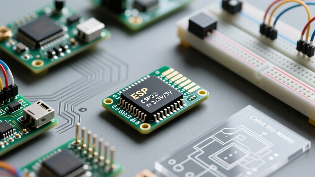
While modern microcontrollers like the ESP32-S3 and Raspberry Pi Pico dominate the headlines, the Arduino Mini (and its ubiquitous third-party sibling, the Arduino Pro Mini) remains a staple in the maker community. By stripping away the onboard USB-to-Serial converter, voltage regulators, and bulky DC jacks, the Mini reduces the board footprint to roughly 1.2 x 0.7 inches. This makes it ideal for permanent, space-constrained embedded installations, battery-powered IoT nodes, and custom PCB designs.
However, this minimalist design introduces a hurdle for beginners: you cannot simply plug it into a USB port to upload code. To program an Arduino Mini, you must use an external USB-to-Serial FTDI adapter. This tutorial provides a deep-dive, step-by-step guide on wiring, configuring, and troubleshooting the upload process, including the infamous 'manual reset' timing trick required for budget adapters.
Bill of Materials (BOM) and Hardware Requirements
Before wiring, ensure you have the correct hardware. Mismatched voltage levels are the number one cause of dead Mini boards. As of 2026, generic FT232RL adapters from overseas marketplaces cost between $3 and $6, while branded breakout boards retail for $12 to $15.
| Component | Specific Model / Variant | Estimated Cost | Critical Notes |
|---|---|---|---|
| Microcontroller | Arduino Mini 05 or SparkFun Pro Mini (DEV-11113) | $4.00 - $16.00 | Verify if you have the 5V/16MHz or 3.3V/8MHz version. |
| FTDI Adapter | FT232RL USB-to-Serial Breakout | $5.00 - $14.00 | Must match the voltage of your Mini (5V or 3.3V). |
| Capacitor | 0.1µF Ceramic Capacitor | $0.10 | Required for auto-reset if your FTDI lacks a DTR pin. |
| Wiring | Silicone Female-to-Male Jumper Wires | $4.00 | 24 AWG silicone wire prevents breadboard pin bending. |
Step 1: Pinout and Wiring the FTDI Adapter
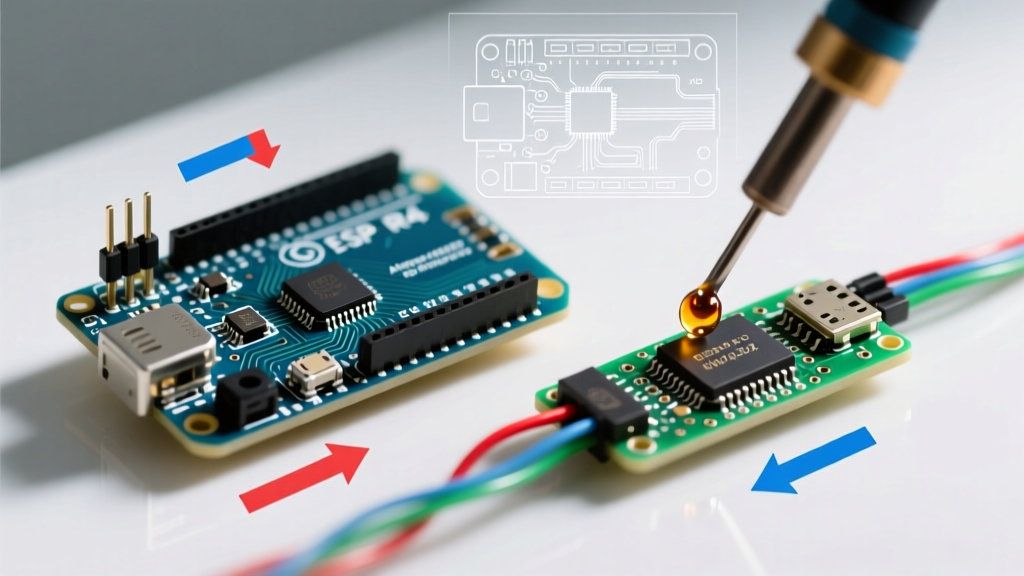
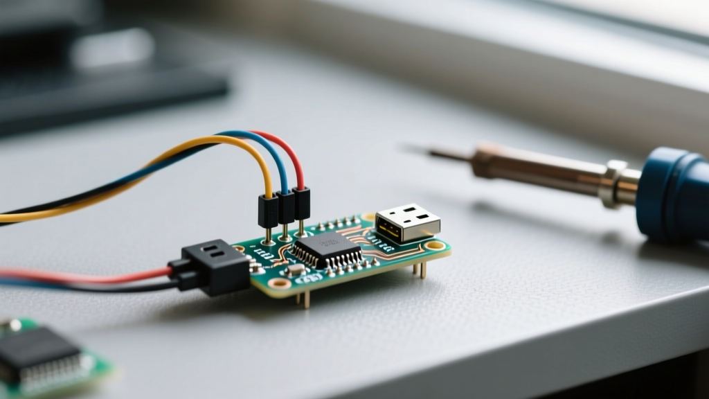
The Arduino Mini utilizes a 6-pin serial header for programming. Your FTDI adapter will also feature a 6-pin header. The golden rule of serial communication is that Transmit (TX) must connect to Receive (RX), and vice versa.
Connect the pins as follows:
- GND to GND: Establishes the common ground reference.
- CTS to Nothing: Clear-to-Send is generally unused for basic Arduino programming. Leave it disconnected.
- VCC to VCC (or 5V/3.3V): WARNING: If your Mini is a 3.3V board, you MUST set your FTDI adapter's voltage jumper to 3.3V. Supplying 5V to a 3.3V Pro Mini will instantly destroy the ATmega328P silicon.
- TXO to RXI: FTDI Transmit connects to Arduino Receive (Pin 0).
- RXI to TXO: FTDI Receive connects to Arduino Transmit (Pin 1).
- DTR to GRN (Reset): This is the most critical and problematic pin. DTR (Data Terminal Ready) pulses low to trigger the auto-reset circuit on the Mini, allowing the bootloader to catch the upload sequence.
Step 2: The DTR Pin Problem and the 0.1µF Capacitor Trick
Many budget FT232RL adapters manufactured in recent years omit the DTR pin, replacing it with CTS or simply leaving it unbroken. Furthermore, some clone Arduino Minis lack the 0.1µF capacitor on the reset line that facilitates capacitive coupling for auto-reset.
If your FTDI adapter has a DTR pin, connect it directly to the GRN (or Reset) pin on the Mini.
If your adapter lacks a DTR pin but has a DTR solder pad on the PCB, you can solder a wire to it. Alternatively, you must perform the Manual Reset Timing Trick (detailed in the troubleshooting section) or add an external 0.1µF capacitor between the RTS/DTR line of your USB bridge and the Mini's reset pin. For a comprehensive look at the official schematic and reset circuitry, refer to the Arduino Mini retired hardware documentation.
Step 3: Arduino IDE Configuration
With the hardware wired, open the Arduino IDE (version 2.x or later). Because the official 'Arduino Mini' is largely retired, the IDE groups it under the Pro Mini architecture.
- Navigate to Tools > Board > Arduino AVR Boards and select Arduino Pro or Pro Mini.
- Go to Tools > Processor. You must select the exact match for your hardware:
- ATmega328P (5V, 16 MHz) - Standard for most USB-powered projects.
- ATmega328P (3.3V, 8 MHz) - Mandatory for battery-powered LiPo projects and direct 3.3V sensor interfacing.
- Select your active COM port under Tools > Port. If the port is grayed out, your FTDI drivers are missing (common with CH340G clone chips on Windows 11).
Understanding Logic Levels: 5V vs 3.3V Ecosystems
A frequent failure mode in 2026 DIY projects is connecting a 5V Arduino Mini directly to modern 3.3V I2C sensors (like the BME280 or SCD40) or ESP-01 Wi-Fi modules. The ATmega328P running at 5V outputs 5V on its SDA/SCL and TX/RX lines. Feeding 5V into the 3.3V logic pins of a modern sensor will degrade or destroy the sensor's internal MOSFETs over time.
The Fix: If you must use a 5V Arduino Mini with 3.3V peripherals, you must use a bidirectional logic level shifter (like the Texas Instruments TXS0108E or a generic BSS138 MOSFET breakout board, costing roughly $1.50). Alternatively, standardizing your entire build around the 3.3V / 8MHz Arduino Mini eliminates the need for level shifters entirely, as 3.3V logic is the modern standard for low-power embedded peripherals.
Troubleshooting Upload Failures
Uploading to an Arduino Mini without native USB is notoriously finicky. Below is a diagnostic matrix for the most common `avrdude` errors encountered during compilation and uploading.
1. 'avrdude: stk500_recv(): programmer is not responding'
Cause: The IDE is attempting to upload, but the ATmega328P bootloader is not active. The board did not reset when the upload began.
Solution (The Manual Reset Trick): If your FTDI lacks a DTR pin, you must manually press and release the physical reset button on the Mini. The timing is exact: click 'Upload' in the IDE, wait for the console to say 'Done compiling', and immediately press and release the reset button. You have a roughly 400-millisecond window before the bootloader times out and hands control back to the user sketch.
Pro-Tip: Add a tactile switch directly across the GND and Reset pins on your breadboard if your Mini's onboard reset button is obscured by a soldered enclosure.
2. 'Board at COMX is not available'
Cause: The USB-to-Serial bridge has dropped off the USB bus, or the port is locked by another process (like a serial monitor left open in another tab or software like Cura/OctoPrint).
Solution: Close all serial terminals. Unplug the FTDI adapter, wait 3 seconds, and plug it back into a different USB root hub (avoid unpowered front-panel case ports). For deeper driver analysis, consult SparkFun's Pro Mini hookup guide, which covers edge cases with counterfeit FT232RL chips being bricked by Windows Update.
3. 'avrdude: verification error, first mismatch at byte 0x0000'
Cause: A voltage brownout during the flash write cycle, or selecting the wrong processor speed in the IDE (e.g., trying to flash a 16MHz bootloader onto an 8MHz crystal board).
Solution: Verify your crystal oscillator. Look at the silver oval component on the Mini board; it will be stamped with '16.000' (16MHz) or '8.000' (8MHz). Match this exactly in the IDE Processor menu. Ensure your FTDI adapter can supply at least 500mA of current; some cheap laptop USB-C hubs throttle current to 100mA, causing the Mini to brownout during the high-current EEPROM write phase.
Conclusion
Mastering the Arduino Mini via an FTDI adapter bridges the gap between beginner-friendly development boards and professional, bare-metal embedded design. By understanding the nuances of the DTR auto-reset circuit, respecting 3.3V vs 5V logic boundaries, and mastering the manual reset timing trick, you can reliably deploy these ultra-compact microcontrollers into permanent, production-grade hardware installations. For further reading on the underlying FT232R chip architecture that powers your adapter, review the official FTDI FT232R datasheet and product pages.