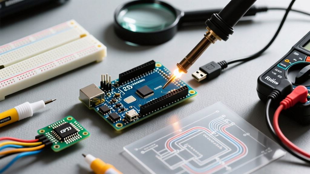

The Anatomy of Arduino 2560 Mega Failures
The Arduino 2560 Mega is the workhorse of the maker community, offering 54 digital I/O pins, 16 analog inputs, and a massive 256KB of flash memory via the ATmega2560 microcontroller. However, its physical size and complex routing make it uniquely susceptible to specific hardware and firmware failures that don't typically plague the smaller Uno or Nano boards. Whether you are dealing with genuine Italian-manufactured Rev3 boards or third-party clones, understanding the underlying architecture is the first step in effective troubleshooting.
In this comprehensive 2026 guide, we bypass generic 'restart your computer' advice and dive straight into component-level diagnostics, addressing the most critical failure modes of the Arduino 2560 Mega, from USB-to-serial handshake timeouts to onboard linear regulator thermal throttling.
Diagnostic Matrix: Symptom to Root Cause
Before opening the IDE console, use this rapid diagnostic matrix to isolate your Arduino 2560 Mega issue based on physical and software symptoms.
| Symptom | Probable Root Cause | Quick Verification Step |
|---|---|---|
| avrdude: stk500v2_ReceiveMessage(): timeout | Auto-reset circuit failure or ATmega16U2 firmware corruption | Perform manual reset timing during upload |
| Board recognized but COM port disappears on upload | USB Polyfuse (PTC) tripping or VBUS short | Measure USB 5V rail with a multimeter during upload |
| ON LED dim, board gets hot near DC jack | NCP1117 linear regulator thermal shutdown | Reduce input voltage to 7.5V or use 5V pin injection |
| Sketch uploads but runs erratically / resets | Brown-out detection (BOD) triggering from noisy power | Check 5V rail for ripple >50mV using an oscilloscope |
| COM port missing entirely (Clone boards) | Missing CH340/CH341G USB-Serial drivers | Check Device Manager for 'Unknown Device' or 'USB-Serial' |
Resolving USB & Upload Timeout Errors
The most notorious error encountered on the Arduino 2560 Mega is the avrdude: stk500v2_ReceiveMessage(): timeout message. Unlike the Uno, which uses the Optiboot bootloader, the Mega uses the STK500v2 bootloader, which has a different handshake timing sequence.
The Auto-Reset Circuit and the 100nF Capacitor
Genuine boards route the DTR (Data Terminal Ready) signal from the ATmega16U2 USB interface chip through a 100nF capacitor (often labeled C13) to the RESET pin of the main ATmega2560. This creates a momentary low-pulse that resets the chip precisely when the IDE initiates the upload. If this capacitor has failed, or if you are using a clone with poor solder joints, the auto-reset fails.
The Manual Reset Workaround:
- Click the Upload button in the Arduino IDE.
- Watch the black console window at the bottom.
- Wait for the compilation to finish and the text 'Sketch uses X bytes...' to appear.
- Immediately press and release the physical RESET button on the Mega.
If the upload succeeds using this method, your auto-reset circuit is compromised. You can permanently fix this by soldering a replacement 100nF ceramic capacitor between the 16U2 DTR line and the ATmega2560 RESET pin, or simply continue using the manual method.
Clone Boards: The CH340G Factor
Most budget-friendly Arduino 2560 Mega clones replace the expensive ATmega16U2 chip with a WCH CH340G or CH341G USB-to-serial converter. If your board is not showing up in the IDE port menu, you are likely missing the specific driver for this chip. You can find the correct driver installation steps via the official Arduino IDE troubleshooting documentation. Ensure you select the correct architecture (ARM vs x64) for your 2026 operating system.
Power Delivery & Thermal Throttling Failures
The power delivery network (PDN) on the Mega is frequently misunderstood, leading to sudden board resets or permanent regulator damage when powering high-draw peripherals like stepper motors or LED matrices.
The 500mA USB Polyfuse (PTC)
Located near the USB port, a resettable PTC (Polymeric Positive Temperature Coefficient) fuse protects your computer's USB hub from shorts. If your sketch and connected shields attempt to draw more than 500mA from the USB VBUS line, the PTC heats up and its resistance spikes, dropping the board voltage to roughly 3V. The ATmega2560 will brown out and reset. Fix: Never power high-current peripherals directly from the USB 5V pin. Use an external power supply routed through the DC barrel jack or the VIN pin.
NCP1117 Linear Regulator Thermal Limits
When using the DC barrel jack, the voltage passes through an onboard linear regulator (typically an NCP1117ST50T3G). Linear regulators dissipate excess voltage as heat. The formula for power dissipation is P = (Vin - 5V) * I.
Expert Warning: If you supply 12V to the barrel jack and draw 300mA from the 5V rail, the regulator must dissipate (12V - 5V) * 0.3A = 2.1 Watts. The NCP1117 SOT-223 package lacks a dedicated heatsink and will hit its 150°C thermal shutdown threshold in under 45 seconds, causing the board to reboot continuously. For optimal thermal performance, keep your barrel jack input between 7V and 9V.
For deeper component specifications, refer to the Arduino Mega 2560 Hardware Documentation to review the exact schematic and power routing.
Bootloader Corruption & ICSP Recovery
If your Arduino 2560 Mega fails to accept uploads, the onboard LED (Pin 13) does not blink on power-up, and manual reset timing fails, the STK500v2 bootloader is likely corrupted. This often happens due to static discharge on I/O pins or brown-outs during flash memory writes.
Flashing via the ICSP Header
You can bypass the USB-to-serial chip entirely and re-flash the bootloader using the 6-pin ICSP (In-Circuit Serial Programming) header located near the main ATmega2560 chip. You will need a dedicated programmer like a USBasp, or a second working Arduino configured as an ISP (In-System Programmer).
ICSP Pinout for the Mega 2560:
- Pin 1: MISO (Master In Slave Out)
- Pin 2: VCC (5V)
- Pin 3: SCK (Serial Clock)
- Pin 4: MOSI (Master Out Slave In)
- Pin 5: RESET
- Pin 6: GND
Connect your USBasp to these pins, select 'USBasp' as the programmer in the Arduino IDE tools menu, and click Burn Bootloader. The IDE utilizes the AVRDUDE utility under the hood to write the bootloader hex file directly to the flash memory and set the correct fuse bits (specifically setting the BOOTRST fuse to direct the execution vector to the bootloader section upon startup).
Peripheral Edge Cases: I2C and Hardware Serial
I2C Bus Hanging (Pins 20 & 21)
The Mega 2560 routes the I2C bus to Pins 20 (SDA) and 21 (SCL), as well as the dedicated header near the USB port. Unlike some modern microcontrollers, the ATmega2560's TWI (Two-Wire Interface) peripheral does not have robust internal pull-up resistors. If you connect an I2C sensor without external 4.7kΩ pull-up resistors to 5V, the bus lines will float, causing the Wire.h library to hang indefinitely. Always verify pull-ups with a multimeter; you should read ~4.7kΩ between SDA/SCL and the 5V rail.
Serial Port Conflicts
The Mega features four hardware serial ports: Serial (Pins 0/1), Serial1 (Pins 18/19), Serial2 (Pins 16/17), and Serial3 (Pins 14/15). A common beginner mistake is wiring a GPS module or Bluetooth HC-05 to Pins 0 and 1. Because Serial (UART0) is hardwired to the USB interface chip, attaching external devices here causes voltage contention during uploads, resulting in corrupted data or upload failures. Always reserve Pins 0 and 1 strictly for PC communication and move external serial peripherals to Serial1, Serial2, or Serial3.
Expert FAQ
Why does my Arduino 2560 Mega clone have a different USB chip?
Manufacturers use the CH340G or CP2102 chips to reduce production costs. The ATmega16U2 requires a separate firmware flash and a crystal oscillator, adding roughly $2.50 to the bill of materials. Clones pass these savings to the consumer, but require specific OS drivers to translate the USB signals to UART.
Can I power the Mega directly via the 5V pin?
Yes, injecting a clean, regulated 5V directly into the '5V' header pin bypasses the onboard NCP1117 regulator and the USB polyfuse. This is the preferred method for robotics projects using 5V UBECs (Universal Battery Eliminator Circuits) powered by LiPo batteries. However, if your injected voltage exceeds 5.5V, you will instantly destroy the ATmega2560 silicon, as there is no protection circuit on this specific pin.
How do I clear a 'Board at COMx is not available' error?
This usually indicates the IDE's serial monitor is holding the port hostage, or a background process (like Cura, PrusaSlicer, or another instance of the IDE) has locked the COM port. Close all 3D printing slicers and serial terminals, unplug the Mega, wait 5 seconds for the host OS to clear the USB device tree, and reconnect.