
The Ultimate DS18B20 Arduino Quick Reference
The Maxim Integrated (now Analog Devices) DS18B20 remains the gold standard for digital temperature sensing in maker projects. Utilizing the 1-Wire protocol, it requires only a single data pin to communicate, making it ideal for multi-sensor arrays, waterproof environmental monitoring, and DIY smart home integrations. However, despite its simplicity, the unique electrical requirements of the 1-Wire bus often trip up both beginners and seasoned engineers.
This FAQ and quick reference guide cuts through the fluff, providing exact wiring schematics, library configurations, and deep-dive troubleshooting for the most common DS18B20 Arduino integration issues encountered in the field.
Quick Reference: DS18B20 Specifications & Pinout
| Parameter | Specification / Value |
|---|---|
| Operating Voltage | 3.0V to 5.5V (Parasitic or External) |
| Temperature Range | -55°C to +125°C |
| Accuracy | ±0.5°C (from -10°C to +85°C) |
| Resolution | User-configurable: 9, 10, 11, or 12-bit |
| Conversion Time | 93.75ms (9-bit) to 750ms (12-bit) |
| Interface | 1-Wire (Requires 4.7kΩ pull-up resistor) |
| Pinout (TO-92) | 1: GND | 2: DQ (Data) | 3: VDD |
Hardware & Wiring FAQ
Why is a 4.7kΩ pull-up resistor mandatory?
The 1-Wire protocol uses an open-drain architecture. The Arduino and the DS18B20 can only pull the data line LOW (to ground); neither can actively drive it HIGH. The 4.7kΩ pull-up resistor connected between the data line (DQ) and VCC (3.3V or 5V) is responsible for pulling the line HIGH when no device is asserting a LOW signal. Without this resistor, the data line will float, resulting in random noise, CRC failures, and a complete inability to read the sensor's unique 64-bit ROM address.
Parasitic vs. External Power Mode: Which should I choose?
The DS18B20 supports two power configurations:
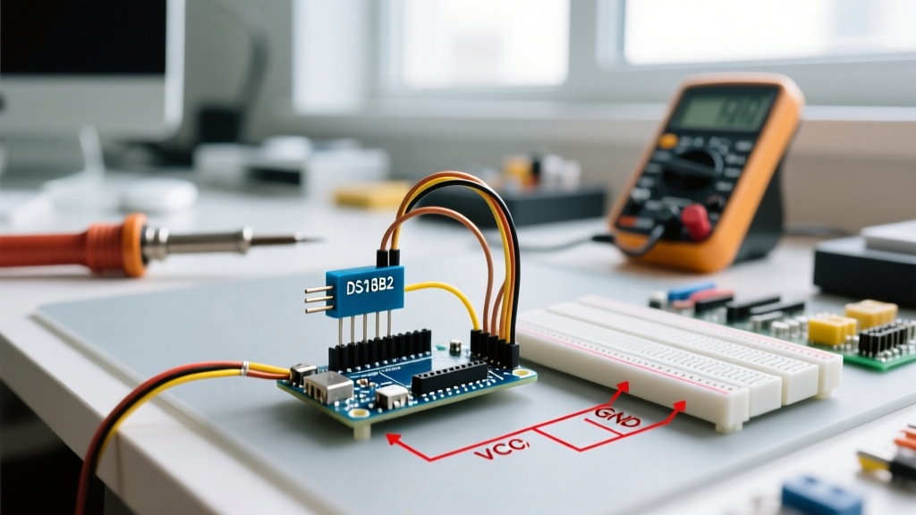
- External Power Mode (Recommended): Pin 1 to GND, Pin 2 to Data, Pin 3 to VCC. This provides a stable power source directly from the Arduino's 5V or 3.3V rail, ensuring reliable temperature conversions and allowing for longer cable runs.
- Parasitic Power Mode: Pin 1 and Pin 3 are both tied to GND. The sensor harvests power from the data line via an internal capacitor while the line is HIGH. While this saves a wire, it is highly susceptible to voltage drops during the 750ms temperature conversion phase, especially if multiple sensors are on the same bus. Use this only for short, single-sensor setups.
Can I wire multiple DS18B20 sensors to a single Arduino pin?
Yes. The 1-Wire protocol is designed as a multi-drop bus. You can wire dozens of DS18B20 sensors in parallel to a single digital pin. Every DS18B20 has a factory-lasered, globally unique 64-bit serial code. The Arduino addresses each sensor individually using this ROM code. However, when wiring multiple sensors, keep the physical bus topology in mind: use a linear 'daisy-chain' or 'star' topology with short stubs, and ensure your 4.7kΩ pull-up resistor is placed at the Arduino end of the bus.
Software & Code FAQ
What libraries are required for 2026 Arduino IDE setups?
To interface with the DS18B20, you need two specific libraries installed via the Arduino Library Manager:
- OneWire by Jim Studt, Tom Pollard, and Paul Stoffregen: Handles the low-level 1-Wire timing and bus communication. You can review the protocol specifics on the PJRC OneWire documentation page.
- DallasTemperature by Miles Burton: Acts as a wrapper over OneWire, translating raw bus data into human-readable Celsius and Fahrenheit floats. The source and examples are maintained on the DallasTemperature GitHub repository.
How do I find the unique 64-bit ROM address of my sensor?
Before you can request temperature data from a specific sensor on a multi-drop bus, you must know its address. Upload the OneWireSearch example sketch included with the OneWire library. Open the Serial Monitor at 9600 baud. The sketch will scan the bus and print the hexadecimal ROM address (e.g., 28 FF 64 1F 86 16 03 5D). Copy this array into your main sketch to target that specific sensor, ensuring your code doesn't break if you swap the physical order of the sensors on the bus.
Troubleshooting & Edge Cases
Why is my sensor reading exactly 85°C?
A reading of exactly 85°C is the most common DS18B20 Arduino issue. This is not a real temperature; it is the sensor's factory default power-on reset (POR) value stored in its scratchpad register. If you see 85°C, it means the Arduino requested the temperature before the sensor completed its analog-to-digital conversion.
The Fix: The 12-bit conversion takes a maximum of 750ms. If you are using parasitic power mode, you must call sensors.setWaitForConversion(false);, trigger the conversion, and then explicitly use delay(750); before requesting the data. If using external power, the DallasTemperature library handles this blocking delay automatically, but if you have modified the code to be non-blocking, ensure you are respecting the conversion timing matrix detailed in the official Analog Devices DS18B20 datasheet.
Why is my sensor reading -127°C?
A reading of -127°C (or sometimes -196°F) is a software-generated error code from the DallasTemperature library indicating a complete communication failure. This happens when the library fails the Cyclic Redundancy Check (CRC) or cannot detect any device on the bus.
Common Causes & Fixes:
- Missing Pull-up Resistor: Verify the 4.7kΩ resistor is connected between VCC and the Data pin.
- Wiring Fault: Check for broken wires, especially in waterproof stainless-steel probe variants where the internal solder joints can fail under mechanical stress.
- Pin Assignment Error: Ensure the digital pin defined in your
OneWire oneWire(PIN)declaration matches the physical pin the data wire is plugged into.
Advanced: Dealing with Long Cable Runs and Capacitance
The 1-Wire protocol is highly sensitive to cable capacitance. Standard CAT5 or 22AWG wire introduces roughly 50pF to 70pF of capacitance per meter. If your waterproof DS18B20 probe cable exceeds 5 meters, the capacitance will slow down the rise time of the data line, causing the Arduino to misread bits and trigger CRC errors.
Pro-Tip for Long Runs: If you must run cables longer than 10 meters, drop the pull-up resistor value from 4.7kΩ down to 2.2kΩ or even 1kΩ to provide a stronger, faster pull-up current. For industrial runs exceeding 20 meters, abandon the passive resistor entirely and use an active 1-Wire master IC (like the DS2480B) or a MOSFET-based active pull-up circuit to forcefully drive the line HIGH.
⚠️ 2026 Counterfeit Sensor Warning: The market is currently flooded with counterfeit DS18B20 chips, particularly in cheap multi-packs from unauthorized online marketplaces. Fake chips often lack the internal EEPROM, fail to hold configuration changes, and exhibit massive thermal lag. Authentic Analog Devices chips feature crisp, laser-etched markings on the TO-92 package, whereas fakes often use painted or stamped text. Always source your sensors from authorized distributors like Mouser, DigiKey, or reputable maker stores to guarantee accurate ±0.5°C readings.
Resolution vs. Conversion Time Matrix
While 12-bit (0.0625°C resolution) is the default, many environmental monitoring projects do not require that level of precision. By lowering the resolution, you can drastically reduce the conversion time, which is critical for battery-powered, sleep-mode Arduino nodes.
| Resolution | Temperature Step | Max Conversion Time |
|---|---|---|
| 9-bit | 0.5°C | 93.75 ms |
| 10-bit | 0.25°C | 187.5 ms |
| 11-bit | 0.125°C | 375 ms |
| 12-bit (Default) | 0.0625°C | 750 ms |
To change the resolution in your code, use the sensors.setResolution(10); command inside your setup() loop. Remember that this setting is written to the sensor's EEPROM, meaning it will persist even after power cycling.