
The Electromagnetic Foundation of Stepper Motors
When integrating a step motor Arduino system into a robotics or CNC project, it is crucial to understand that stepper motors do not operate like standard brushed DC motors. Instead of continuous rotation driven by a commutator, a stepper motor translates discrete electrical pulses into precise mechanical angular movements. The rotor contains permanent magnets, while the stator houses multiple electromagnetic coils. By energizing these coils in a specific sequence, the magnetic field pulls the rotor teeth into alignment, creating a 'step'.
The industry standard for desktop 3D printers, laser engravers, and general maker projects is the NEMA 17 frame size, specifically bipolar models like the 17HS4401S. This motor features a 1.8-degree step angle, yielding exactly 200 full steps per revolution. With a typical holding torque of 40 Ncm (Newton-centimeters) and a rated current of 1.2A per phase, it provides the ideal balance of precision and force for light-to-medium duty automation.
Driver Selection Matrix: A4988 vs. DRV8825 vs. TMC2209
An Arduino Uno or Nano operates at 5V logic and can source a maximum of 40mA per I/O pin. A NEMA 17 stepper requires upwards of 1.2A to 2.0A per phase at voltages ranging from 12V to 24V. Therefore, you cannot wire a step motor directly to an Arduino. You must use a dedicated stepper driver IC that acts as a high-current translator. Below is a 2026 market comparison of the three most prevalent driver modules:
| Driver IC | Max Continuous Current | Microstepping Resolution | Avg. Module Price (2026) | Acoustic Noise Profile |
|---|---|---|---|---|
| A4988 | 1.0A (without active cooling) | Up to 1/16 step | $2.50 - $3.50 | Audible whine at high speeds |
| DRV8825 | 1.5A (without active cooling) | Up to 1/32 step | $4.00 - $5.50 | Moderate, slightly quieter |
| TMC2209 | 2.0A (RMS) with StealthChop | Up to 1/256 step (interpolated) | $8.00 - $11.00 | Virtually silent |
For budget-conscious prototyping, the A4988 remains a staple. However, for applications requiring acoustic discretion (such as camera sliders or medical automation), the Trinamic-designed Analog Devices TMC2209 is the definitive choice, utilizing proprietary StealthChop PWM modulation to eliminate low-speed resonance noise.
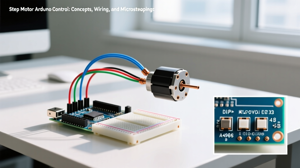
Wiring a Step Motor to Arduino via A4988
Proper wiring is critical. A bipolar stepper motor has four wires, typically organized into two coils (Phase A and Phase B). To identify the coils without a datasheet, use a multimeter in continuity mode. Wires that show low resistance (usually 2 to 5 ohms) belong to the same coil pair.
Step-by-Step Wiring Guide
- Power Supply: Connect a 12V or 24V DC power supply to the driver's VMOT and GND pins. Crucial: Place a 100µF electrolytic capacitor across VMOT and GND to absorb inductive voltage spikes.
- Logic Level: Connect the Arduino 5V pin to the driver's VDD pin to power the internal logic gates.
- Ground Reference: Tie the Arduino GND to the driver's GND. A shared ground is mandatory for signal integrity.
- Control Pins: Wire the driver's STEP pin to Arduino Pin 3, and the DIR (Direction) pin to Arduino Pin 4.
- Motor Coils: Connect Coil A (e.g., Black and Green wires) to 1A and 1B. Connect Coil B (e.g., Red and Blue wires) to 2A and 2B.
CRITICAL WARNING: Never disconnect or reconnect the stepper motor wires from the driver while the VMOT power supply is active. Doing so will cause an inductive kickback that will instantly destroy the driver's internal MOSFETs, permanently bricking the module.
Setting the Current Limit (Vref)
Before uploading code, you must calibrate the driver's current limit to match your motor's rated current. Sending 2.0A to a motor rated for 1.2A will overheat the windings and degrade the permanent magnets. According to Texas Instruments Stepper Motor Basics, current regulation is managed via a reference voltage (Vref). For a standard A4988 module with Rsense = 0.1Ω, the formula is:
Vref = Imot * 8 * Rsense
For a 1.2A motor: 1.2 * 8 * 0.1 = 0.96V. Use a multimeter to measure the voltage between the Vref potentiometer wiper and ground, adjusting the trimpot until you hit exactly 0.96V.
The Mathematics and Trade-offs of Microstepping
Full-stepping energizes the coils in a binary sequence (ON/OFF). This causes the rotor to snap aggressively from one position to the next, resulting in vibration, mechanical resonance, and noise. Microstepping solves this by proportionally modulating the current in the two coils to follow sine and cosine waveforms.
By dividing the current into smaller increments, the magnetic equilibrium point shifts fractionally between the physical stator teeth. A 1/16 microstep setting on a 200-step motor yields 3,200 steps per revolution, reducing the angular resolution to 0.1125 degrees. However, there is a fundamental physics trade-off: incremental holding torque drops exponentially as microstep resolution increases.
- Full Step: 100% of rated holding torque.
- 1/2 Step: ~71% of rated holding torque.
- 1/16 Step: ~9.8% incremental torque per microstep.
- 1/32 Step: ~4.9% incremental torque per microstep.
At 1/32 or 1/256 microstepping, the incremental torque becomes so small that external mechanical loads, friction, or belt tension can easily prevent the rotor from moving to the next microstep. The driver will output the electrical pulse, but the motor will physically 'skip' the microstep, accumulating positional error. Therefore, 1/16 microstepping remains the optimal sweet spot for most CNC and 3D printing applications.
Programming: Why AccelStepper is Mandatory
Beginners often attempt to control a step motor Arduino setup using basic digitalWrite() loops with fixed delayMicroseconds() intervals. This approach almost always fails under real-world loads due to inertia. A rotor and its attached load possess mass; they cannot instantly accelerate from 0 to 1,000 RPM. If the Arduino pulses the STEP pin faster than the rotor's magnetic field can physically pull the load, the motor will stall, vibrate violently, and miss steps.
To manage inertia, you must implement acceleration and deceleration ramps. The canonical solution is Mike McCauley's AccelStepper Library. This library calculates trapezoidal or triangular velocity profiles in the background via non-blocking timers.
Implementation Logic
#include <AccelStepper.h>
// Define a stepper and the pins it will use
AccelStepper stepper(AccelStepper::DRIVER, 3, 4); // STEP=3, DIR=4

void setup() {
  stepper.setMaxSpeed(1000.0);      // Max speed in steps/second
  stepper.setAcceleration(400.0);   // Acceleration in steps/second^2
  stepper.setCurrentPosition(0);
  stepper.moveTo(6400);             // Move 2 full rotations (at 1/16 microstepping)
}

void loop() {
  stepper.run(); // Must be called continuously to process the ramp
}
By defining a max speed of 1000 steps/sec and an acceleration of 400 steps/sec², the library smoothly ramps the motor up to speed, preventing the low-speed resonance stall that plagues basic delay() scripts.
Real-World Failure Modes and Edge Cases
Even with perfect wiring and code, step motor systems encounter distinct failure modes in the field. Recognizing these edge cases separates amateur builds from reliable industrial prototypes.
- Mid-Range Resonance: Stepper motors exhibit a severe torque dip and tendency to stall between 150 and 300 RPM (roughly 500 to 1000 full steps/sec). This is caused by the rotor overshooting the target equilibrium point and oscillating. Solution: Accelerate rapidly through this RPM band, or enable microstepping and mechanical dampers.
- Thermal Throttling and Shutdown: Driver ICs like the DRV8825 feature internal over-temperature shutdown (typically around 150°C). If the driver lacks a heatsink or active airflow, it will silently cut power to the coils when it overheats, causing the motor to drop its holding torque and lose position. Solution: Adhere a copper heatsink and ensure enclosure ventilation.
- Inductive Voltage Spikes: Long cable runs between the driver and the motor act as antennas and increase parasitic inductance. When the driver's H-bridge switches off, the collapsing magnetic field generates high-voltage spikes that can exceed the 35V breakdown limit of the A4988. Solution: Keep motor wires under 2 meters and twist the Phase A and Phase B wire pairs to cancel electromagnetic interference (EMI).
By mastering the electromagnetic concepts, calculating precise Vref limits, and leveraging algorithmic acceleration ramps, your step motor Arduino projects will achieve the sub-millimeter precision required for advanced automation and robotics.