
The Definitive Community Roundup: Pushbutton Wiring and Debouncing
Learning how to connect button to Arduino microcontrollers is a foundational rite of passage for every maker. Yet, despite its apparent simplicity, pushbutton integration remains the source of nearly 90% of beginner-level hardware headaches. Floating pins, electromagnetic interference (EMI), and mechanical contact bounce can turn a simple input into an erratic nightmare.
To separate myth from engineering reality, the ElectricalFlux team has compiled a comprehensive 2026 community resource roundup. We polled active GitHub repositories, maker forums, and professional embedded engineers to bring you the most reliable hardware selections, wiring topologies, and software debouncing strategies available today.
1. Hardware Selection: Community-Approved Tactile Switches
Not all buttons are created equal. The community consensus heavily favors specific tactile switch families that offer consistent actuation forces, low contact resistance, and high lifecycle ratings. When sourcing components from distributors like Mouser or DigiKey, these are the gold standards for breadboard and PCB integration.
| Switch Model | Actuation Force | Lifecycle | Avg. Price (2026) | Best Use Case |
|---|---|---|---|---|
| Omron B3F-1000 | 160 gf | 100,000 cycles | $0.12 - $0.18 | Standard breadboard prototyping |
| C&K PTS645 Series | 130 gf | 100,000 cycles | $0.08 - $0.15 | Compact PCB wearables |
| ALPS SKHLLA | 180 gf | 200,000 cycles | $0.20 - $0.28 | Industrial/High-reliability panels |
Community Pro-Tip: Avoid unbranded, ultra-cheap 6x6mm tactile switches from bulk marketplace bins. Their internal metal reeds often suffer from severe oxidation and inconsistent bounce times exceeding 15ms, making software debouncing highly unreliable.
2. Wiring Topologies: Pull-Up vs. Pull-Down
When figuring out how to connect button to Arduino pins, you must prevent the pin from "floating" when the switch is open. A floating pin acts as an antenna, picking up ambient EMI from nearby motors, relays, or even fluorescent lighting.
The Internal Pull-Up Standard (Active-Low)
The most universally recommended approach in the Arduino community utilizes the microcontroller's internal pull-up resistors. On the classic ATmega328P (Arduino Uno/Nano), the internal pull-up is approximately 32kΩ. On the ESP32, it is typically 45kΩ.
- Wiring: Connect one leg of the button to GND, and the opposite leg to your chosen digital input pin (e.g., Pin 2).
- Code: Use
pinMode(2, INPUT_PULLUP); - Logic: The pin reads
HIGHwhen released, andLOWwhen pressed. This eliminates the need for external resistors, saving board space and BOM costs.
The External Pull-Down (Active-High)
While internal pull-ups are convenient, some specific scenarios—such as interfacing with legacy PLCs or specific shift registers—require an active-high logic (pin reads HIGH when pressed). Note that many ESP32 pins lack internal pull-down capabilities, making external resistors mandatory.
- Wiring: Connect a 10kΩ resistor from the input pin to GND. Connect the button between the input pin and 5V (or 3.3V).
- Math: A 10kΩ resistor limits current to 0.5mA at 5V, providing a strong enough logic bias to overcome ambient noise without wasting excessive power.
For a deeper dive into microcontroller pin configurations, refer to the official Arduino Digital Pins Documentation, which details the internal architecture of AVR and ARM-based I/O.
3. The Bounce Problem: Hardware vs. Software Solutions
Mechanical switches do not close cleanly. When the metal contacts meet, they physically bounce micro-welding and breaking the circuit for 1 to 5 milliseconds. To the Arduino, running at 16MHz, this looks like 50 rapid button presses. You must implement debouncing.
Community Library Roundup (Software Debounce)
Rather than writing custom millis() delay loops, the community relies on battle-tested libraries. Here is how the top three contenders compare in 2026:
| Library Name | Author | Key Features | Memory Footprint | Verdict |
|---|---|---|---|---|
| Bounce2 | Thomas O. Fredericks | State change detection, interval tuning | Low | Best for simple, single-button inputs |
| OneButton | Matthias Hertel | Click, double-click, long-press events | Medium | Best for complex UI navigation |
| JC_Button | JChristensen | Auto-repeat, highly optimized polling | Low | Best for industrial menu scrolling |
Hardware Debouncing: The RC Low-Pass Filter
In high-EMI environments (like CNC machines or automotive applications), software debouncing can fail if the EMI causes voltage spikes that mimic switch closures. The community standard for hardware debouncing is the RC (Resistor-Capacitor) filter paired with a Schmitt trigger.
- Place a 1kΩ series resistor between the switch and the microcontroller pin.
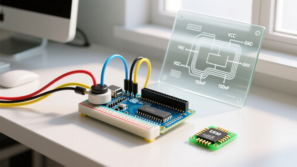
- Place a 100nF (0.1µF) ceramic capacitor from the microcontroller pin to GND.
- The Math: The time constant ($\tau = R \times C$) is $1000 \times 0.0000001 = 0.1ms$. The capacitor will take roughly $5\tau$ (0.5ms) to charge/discharge, effectively smoothing out the 1-5ms mechanical bounce before the microcontroller ever sees it.
For an excellent physics-based breakdown of contact bounce and RC filtering, check out this classic but evergreen technical deep-dive on Hackaday's Embed with Elliot series.
4. Real-World Failure Modes and Troubleshooting
Even with perfect code, physical hardware degrades. Here are the most common failure modes encountered by field technicians and how to resolve them.
Contact Oxidation and "Ghost" Presses
Over time, sulfur and moisture in the air create a non-conductive oxide layer on the switch's internal metal reeds. This manifests as the Arduino failing to register a press, or requiring multiple hard presses to work.
- Fix: For sealed switches, replacement is the only permanent fix. For open-frame switches, a drop of 99% isopropyl alcohol (IPA) and rapid actuation can temporarily clean the contacts.
- Prevention: Specify switches with gold-plated contacts (like the C&K PTS645V series) if your project will be deployed in high-humidity environments.
Breadboard Contact Fatigue
If your button works perfectly on a breadboard but fails when moved, the issue is likely breadboard spring-clip fatigue. Cheap breadboards lose their gripping force after a few component swaps.
- Fix: Never use standard 0.5mm tactile switch legs directly in heavily used breadboards. Solder male header pins to the switch legs, or use a breakout board. The 0.65mm header pins create a much more reliable friction fit with the breadboard's internal leaf springs.
5. Summary: The 2026 Best-Practice Checklist
Before finalizing your schematic or pushing your code to production, run through this community-verified checklist:
- Topology: Are you using
INPUT_PULLUPto save external components? - Debounce: Have you implemented a 10ms software debounce window using a proven library like Bounce2?
- Hardware: Are you using a reputable switch brand (Omron, C&K) to avoid erratic bounce times?
- Protection: If the button is on a long wire (>1 meter), have you added a 100nF hardware filter capacitor to block EMI?
Understanding how to connect button to Arduino systems is about more than just closing a circuit; it is about managing physics, electrical noise, and software state machines. By leveraging the collective wisdom of the maker community and adhering to these engineering standards, your input interfaces will be rock-solid, responsive, and ready for the real world.
For further reading on configuring pin modes and internal resistor states, consult the official Arduino pinMode() Reference.