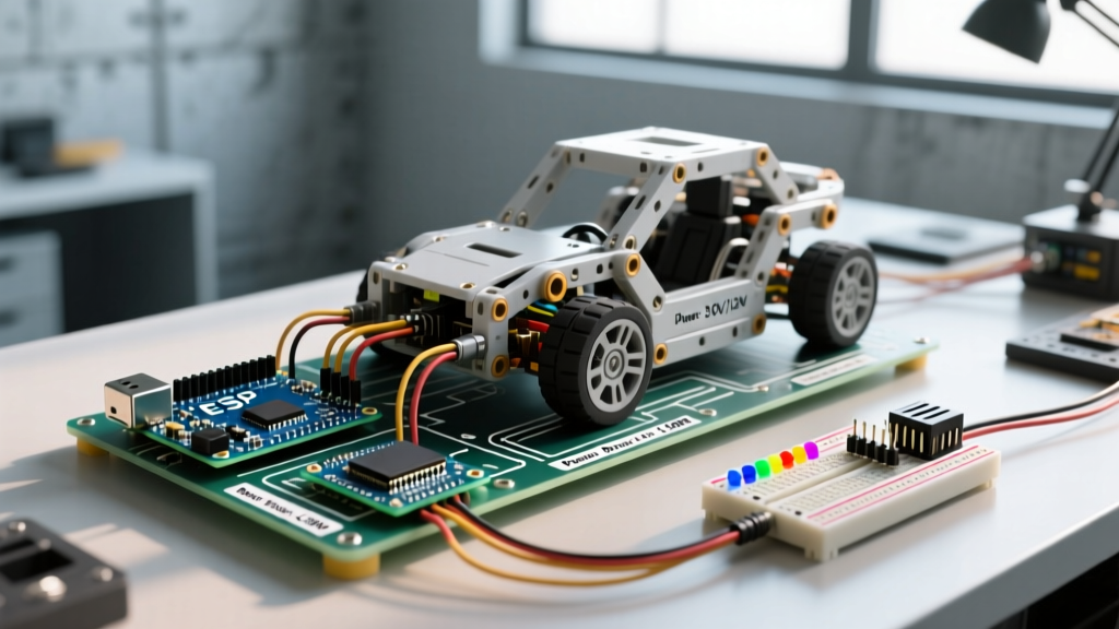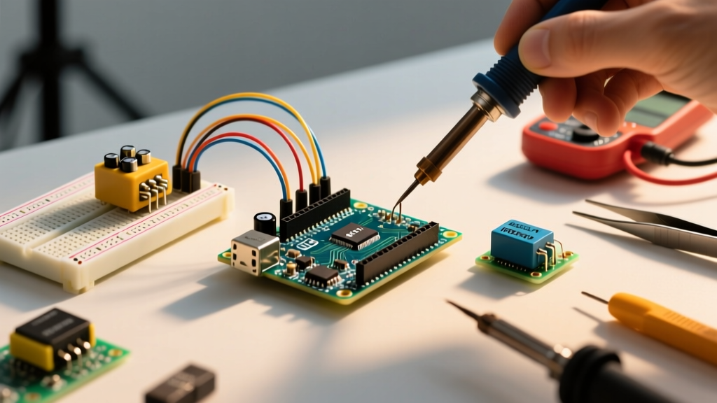

The Hidden Bottleneck in Your Maker Projects
Every veteran maker knows the distinct, acrid smell of a burning AMS1117 voltage regulator. It is a rite of passage that usually happens when you pair a 12V wall adapter with a motor shield drawing 500mA. Selecting the correct power supply for Arduino boards is rarely as simple as matching a barrel jack size. It requires a deep understanding of onboard linear regulators, thermal dissipation limits, and peripheral current draws.
In this compatibility guide, we break down exactly how to match power sources to specific Arduino architectures (from the classic Uno R3 to the modern Uno R4 and Nano 33 BLE), ensuring your project survives long-term deployment without triggering thermal shutdowns or brownout resets.
Anatomy of Arduino Power Inputs
Before selecting a power supply, you must understand the three primary ways power enters an Arduino ecosystem and how the board processes it:
- USB Port (5V Direct): Bypasses the main linear regulator. Power goes through a resettable PTC polyfuse (typically rated for 500mA hold current) directly to the 5V rail. Ideal for low-to-medium power projects.
- Barrel Jack / VIN Pin (7V-12V): Routes through the onboard linear regulator (usually an NCP1117-5.0 or AMS1117-5.0). This converts excess voltage into heat. The higher the input voltage, the less current you can safely draw from the 5V pin.
- 5V Pin (Direct Injection): Bypasses both the USB polyfuse and the linear regulator. This is the most efficient method for high-current projects but offers zero reverse-polarity or overvoltage protection. A 5V 3A buck converter is the gold standard here.
Board-by-Board Power Compatibility Matrix
Not all Arduinos are created equal. The transition to ARM-based and newer AVR chips has drastically changed power architectures. Below is a compatibility matrix for common boards as of 2026.
| Board Model | Onboard Regulator | Recommended VIN | Max 5V/3.3V Pin Draw | Best Power Supply Type |
|---|---|---|---|---|
| Uno R3 / Mega 2560 | NCP1117-5.0 (Linear) | 7V - 9V | ~800mA (Thermally limited) | 9V 1A DC Adapter |
| Uno R4 Minima | RA4M1 Internal / Buck | 6V - 24V | Up to 1.5A (High efficiency) | 12V 2A DC Adapter |
| Nano (Classic AVR) | AMS1117-5.0 (Linear) | 7V - 9V | ~500mA | USB 5V 2A or 7V DC |
| Nano 33 BLE / IoT | AP2112 (3.3V Linear) | 4.5V - 21V (VIN) | ~300mA (at 3.3V) | USB 5V or 5V to VIN |
| ESP32 DevKit V1 | AMS1117-3.3 (Linear) | 5V (USB/Micro) | ~500mA (at 3.3V) | USB 5V 3A (High peak) |
Note: The Arduino Uno R4 Minima features a vastly superior power architecture compared to the R3, utilizing a switching regulator that can handle up to 24V input without the severe thermal penalties of older linear designs.
The Thermal Math: Why 12V Can Destroy Your 5V Rail
To understand why your power supply for Arduino projects must be carefully matched, we need to look at heat dissipation. Linear regulators operate by burning off excess voltage as heat. The formula for power dissipated as heat is:
P_dissipated = (V_in - V_out) × I_load
Let us run a real-world scenario. You are using a classic Arduino Uno R3 to power a 4-channel relay shield. Each relay coil draws roughly 150mA. Total current draw on the 5V rail is 600mA (0.6A).
- Scenario A (9V Adapter): (9V - 5V) × 0.6A = 2.4 Watts of heat.
- Scenario B (12V Adapter): (12V - 5V) × 0.6A = 4.2 Watts of heat.
The SOT-223 package used for the NCP1117 on the Uno R3 has a thermal resistance of roughly 50°C/W to ambient. In Scenario B, the regulator's junction temperature will rise by over 200°C above ambient, instantly triggering internal thermal shutdown (typically at 150°C) or permanently damaging the silicon. According to the ON Semiconductor NCP1117 datasheet, keeping the junction temperature below 125°C requires either massive heatsinks or dropping the input voltage closer to the 7V dropout threshold.
Shield and Peripheral Compatibility Guide
Your board is only half the equation. Shields and external modules dictate your actual current requirements.
1. Relay Modules and Solenoids
Mechanical relays are current hogs. A standard 5V Songle SRD-05VDC-SL-C relay draws about 90mA to 150mA when the coil is energized. If you are using an 8-relay shield, you are looking at 1.2A of continuous draw. Never power an 8-relay shield through the Arduino barrel jack. Use a dedicated 5V 3A switching power supply wired directly to the relay module's JD-VCC and GND pins, sharing only a common ground with the Arduino.
2. Addressable LEDs (WS2812B / NeoPixels)
WS2812B LEDs draw up to 60mA per pixel at full white brightness. A strip of 60 pixels can pull 3.6A. The Arduino's onboard 5V trace and USB polyfuse will melt or trip long before the LEDs reach full brightness. You must inject power directly into the LED strip's 5V and GND lines using an external 5V 10A (50W) power supply.
3. Motor Drivers (L298N, TB6612FNG)
While the logic side of a motor driver draws minimal current (under 50mA), the motors themselves can stall and draw 2A+ per channel. As highlighted in SparkFun's guide on voltage regulators, separating high-current inductive loads from sensitive microcontroller logic is mandatory to prevent back-EMF spikes from resetting your MCU.
Recommended Power Supply Configurations for 2026
Based on project scale, here are the most reliable, cost-effective power supply architectures available today.
Configuration A: The Desktop Prototype (Low Power)
- Use Case: Sensors, I2C OLED displays, single servos.
- Hardware: High-quality USB-C wall charger (5V 2A minimum) + data cable.
- Cost: ~$10.
- Why it works: Bypasses the linear regulator entirely. Modern GaN chargers provide exceptionally clean 5V rails with minimal ripple.
Configuration B: The Enclosed IoT Node (Medium Power)
- Use Case: ESP32 with relays, environmental sensors, LoRa modules.
- Hardware: Mean Well LRS-35-5 (AC to 5V DC enclosed supply) or an MP1584EN buck converter module if stepping down from a 12V battery.
- Cost: $12 - $18.
- Why it works: The MP1584EN is a switching regulator that handles up to 3A with minimal heat generation. Wire 12V into the MP1584EN, step it down to exactly 5.1V, and feed it directly into the Arduino's 5V pin. This yields 90%+ efficiency compared to the 40% efficiency of the onboard linear regulator.
Configuration C: The Robotics Platform (High Power / Split Supply)
- Use Case: Arduino Mega with 4 DC motors, ultrasonic array, and servo pan/tilt.
- Hardware: 3S LiPo Battery (11.1V) + Dual-output BEC (Battery Eliminator Circuit).
- Cost: $25 - $40.
- Why it works: Feed the 11.1V LiPo directly to the motor driver's high-voltage terminals. Use a switching BEC to step the 11.1V down to 6V for the servo rail, and a secondary 5V regulator for the Arduino's VIN pin. This isolates motor noise from the microcontroller's ADC and logic circuits.
Edge Cases and Common Wiring Mistakes
Even with the right power supply for Arduino, improper wiring can lead to catastrophic failure. Watch out for these edge cases:
- The Backfeeding Hazard: If you connect a 5V source to the 5V pin while simultaneously plugging in a USB cable, you risk backfeeding current into your computer's USB port or fighting the onboard USB polyfuse. Always use a DPDT switch to isolate USB power from external 5V injection if both are physically present.
- Clone Board Deficiencies: Many sub-$8 Arduino clones sourced from generic marketplaces omit the reverse-polarity protection diode on the barrel jack. If you use a cheap, unregulated wall adapter with reversed center-polarity, you will instantly fry the microcontroller. Always verify adapter polarity with a multimeter before connecting to clone boards.
- Ground Loops in Audio/ADC Projects: When using external power supplies for audio shields or high-resolution ADCs, digital noise from switching regulators can corrupt readings. Use an LC filter (a 100µH inductor and a 100µF capacitor) on the 5V line feeding the analog components to smooth out high-frequency switching ripple.
Final Verdict
The era of blindly plugging a random 12V wall wart into an Arduino Uno is over. As projects grow to include power-hungry ESP32 modules, high-torque servos, and dense LED arrays, treating your power architecture as a primary design constraint—not an afterthought—is essential. By matching your input voltage to the board's specific regulator topology and utilizing external switching buck converters for heavy loads, you guarantee stable, reset-free operation for your embedded systems.