
The Evolution of the Arduino Flight Controller
When hobbyists first began building DIY quadcopters, the Arduino flight controller was synonymous with the Arduino Mega 2560 running MultiWii or early ArduPilot firmware. However, as we navigate the drone landscape in 2026, the definition and capabilities of Arduino-based flight control have radically shifted. Modern multirotors and fixed-wing UAVs demand sub-millisecond sensor fusion, high-frequency PID loops (4kHz to 8kHz), and DMA-driven motor protocols. This compatibility guide dissects which Arduino boards, IMU sensors, and ESC protocols are actually viable for flight control today, separating legacy toys from professional-grade DIY platforms.
Microcontroller Board Compatibility Matrix
Not all Arduino boards possess the computational overhead or hardware timers required for stable flight. Below is a compatibility matrix evaluating popular Arduino ecosystem boards against modern flight control requirements.
| Board Model | MCU Architecture | Clock Speed | FPU | Flight Control Viability | Approx. Cost (2026) |
|---|---|---|---|---|---|
| Arduino Mega 2560 | 8-bit AVR | 16 MHz | No | Poor (Rovers/Boats only) | $12 - $15 |
| Nano 33 BLE Sense Rev2 | 32-bit ARM Cortex-M4F | 64 MHz | Yes | Good (Micro-drones, AI edge) | $35 - $40 |
| Portenta H7 | Dual ARM Cortex-M7/M4 | 480 MHz | Yes | Excellent (Companion + FC hybrid) | $110 - $125 |
| STM32F405 (SpeedyBee/Matek) | 32-bit ARM Cortex-M4 | 168 MHz | Yes | Industry Standard (ArduPilot/iNav) | $30 - $45 |
While dedicated STM32 flight controllers dominate the commercial market, the Arduino Portenta H7 has emerged as a powerhouse for advanced makers. Its dual-core architecture allows the Cortex-M4 to handle real-time sensor polling and motor outputs, while the Cortex-M7 runs complex computer vision or ROS 2 nodes natively.
IMU and Sensor Integration: I2C vs. SPI Speeds
The Inertial Measurement Unit (IMU) is the heartbeat of any Arduino flight controller. The communication protocol between the MCU and the IMU dictates your maximum PID loop frequency and susceptibility to vibration-induced noise.
The I2C Bottleneck and Clock Stretching
Legacy setups often paired an Arduino Uno or Mega with an MPU6050 via I2C. In 2026, this is strongly discouraged for aerial platforms. I2C is highly susceptible to electromagnetic interference (EMI) from brushless motors. Furthermore, I2C clock stretching—a mechanism where the sensor delays the master clock to process data—introduces unpredictable latency spikes. In a 4kHz PID loop, a 200-microsecond I2C delay causes catastrophic phase lag, leading to quadcopter oscillations or flyaways.
SPI and Modern Sensor Compatibility
For stable flight, SPI (Serial Peripheral Interface) is mandatory. SPI allows for full-duplex communication and clock speeds up to 20MHz, ensuring IMU data is fetched in under 10 microseconds.
- ICM-42688-P (TDK InvenSense): The current gold standard. Supports up to 32kHz sampling rates, ultra-low noise gyroscopes, and hardware anti-aliasing filters. Fully compatible with the Arduino Portenta H7 and STM32F405 boards via hardware SPI.
- BMI270 (Bosch): Excellent for ArduPilot setups, featuring a specialized drone-specific API that offloads gesture and calibration computations from the main MCU.
- LSM9DS1 / LSM6DSOX: Found on the Arduino Nano 33 BLE Sense series. While adequate for sub-250g micro-drones, the noise density is higher than the ICM-42688, requiring aggressive software low-pass filtering.
Expert Troubleshooting Tip: If your custom Arduino sketch exhibits random motor twitches during high-throttle maneuvers, check your SPI chip select (CS) line routing. Keep the CS and MISO traces under 5cm, and place a 10kΩ pull-up resistor on the MISO line to prevent floating states during MCU boot-up.
ESC and Motor Protocol Compatibility
An Arduino flight controller must command Electronic Speed Controllers (ESCs) with absolute precision. The era of analog PWM (50-400Hz) is over for performance drones. Modern protocols require hardware timers and Direct Memory Access (DMA) to prevent CPU blocking.
Protocol Breakdown and Hardware Requirements
- Standard PWM (50-400Hz): Supported by all Arduino boards via the
Servo.hlibrary or hardware timers. Limitation: 400Hz maximum update rate introduces severe latency in aggressive acrobatic flight. - OneShot125 (125-250µs pulse): Requires 16-bit hardware timers. Viable on Arduino Mega 2560, but consumes significant CPU cycles to maintain pulse accuracy.
- DShot600 / DShot1200: A digital protocol sending binary data packets via UART/DMA. Compatibility: 8-bit AVR Arduinos cannot reliably generate DShot signals due to lack of DMA and insufficient clock speed. You must use a 32-bit ARM board (Portenta H7, Nano 33 BLE, or STM32) utilizing STM32duino or native HAL libraries to trigger DMA-based pulse trains.
- Bidirectional DShot (BDShot): Essential for RPM filtering in ArduPilot and Betaflight. The ESC sends telemetry back to the flight controller on the same wire. This requires advanced DMA half-duplex UART configuration, natively supported by the ArduPilot ecosystem on STM32 and Portenta architectures.
Receiver (RX) Protocols: UART and Interrupt Limits
Interfacing with modern RC receivers like ExpressLRS (ELRS) or TBS Crossfire requires specific UART handling.
- SBUS: Runs at 100,000 baud with inverted signaling. The Arduino Mega 2560 requires an external hardware inverter chip (like the 74LS04) to read SBUS. The Portenta H7 and STM32F405 feature native UART inversion via software registers.
- CRSF (Crossfire Serial Protocol): Runs at 420,000 baud (or higher for ELRS). Requires a dedicated hardware UART port and low-latency interrupt service routines (ISRs). Using software serial (
SoftwareSerial.h) on any Arduino board for CRSF will result in dropped packets and failsafe triggers.
Power Architecture and Common Failure Modes
The most common cause of Arduino flight controller failure is not software bugs, but power brownouts. When four brushless motors spool up simultaneously, they can pull 100+ Amps, causing massive voltage sag and injecting high-frequency EMI into the 5V and 3.3V rails.
Designing a Robust Power Train
Never power a flight controller directly from the raw VBAT line or a cheap linear regulator. Implement the following power filtering stage:
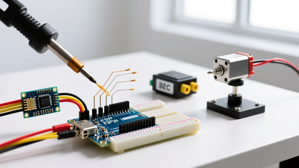
- Primary BEC: Use a high-quality switching BEC rated for at least 5V / 3A continuous (e.g., Matek Systems or Pololu D24V50F5).
- LC Filter Stage: Place a 100µH shielded power inductor in series with the 5V input, followed by a 470µF low-ESR ceramic capacitor bank to ground. This blocks high-frequency motor noise.
- Secondary LDO: For the IMU and barometer, use a dedicated ultra-low noise 3.3V LDO (like the AMS1117-3.3 or AP2112K-3.3) fed from the filtered 5V rail. This ensures clean analog-to-digital conversion (ADC) readings.
Firmware Ecosystem: Custom Sketches vs. ArduPilot
While writing a custom PID loop in the Arduino IDE is an excellent educational exercise, it is rarely safe for beyond-visual-line-of-sight (BVLOS) or heavy-lift drones in 2026. For mission-critical applications, makers should utilize the Arduino Portenta H7 or STM32 boards to run ArduPilot or PX4. These open-source autopilots feature years of edge-case handling, EKF3 (Extended Kalman Filter) sensor fusion, and failsafe redundancies that a custom 500-line Arduino sketch simply cannot replicate.
However, for AI-driven swarm robotics, indoor optical-flow navigation, or educational micro-drones, the Arduino Nano 33 BLE Sense and Portenta H7 running custom TensorFlow Lite Micro models alongside lightweight custom PID loops represent the cutting edge of maker innovation.
Summary Checklist for 2026 Builds
- Ditch 8-bit AVRs for aerial platforms; upgrade to 32-bit ARM Cortex-M.
- Mandate SPI for IMU communication; avoid I2C for primary flight sensors.
- Use DMA-driven DShot600 for ESC telemetry and RPM filtering.
- Implement hardware LC filters to prevent brownout resets.
- Reserve custom Arduino sketches for micro-drones and AI edge computing; rely on ArduPilot for autonomous GPS navigation.