
Quick-Reference Hardware Matrix
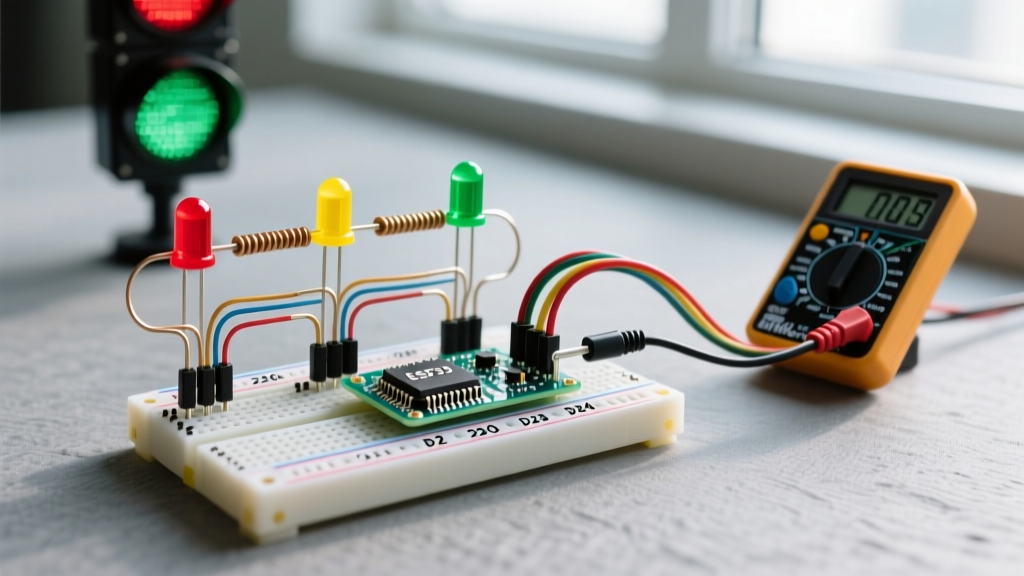
Building an Arduino traffic light is a foundational rite of passage for makers, but moving from a simple blinking LED to a responsive, multi-intersection model requires precise hardware matching. In 2026, with the Arduino Uno R4 Minima retailing around $20 and the classic Uno R3 hovering near $27, understanding the voltage differences between 5V and 3.3V logic boards is critical to prevent component damage or dim outputs.
Below is the quick-reference matrix for standard 5mm through-hole LEDs used in traffic light models. Always calculate your current-limiting resistors based on your specific board's logic level.
| LED Color | Forward Voltage (Vf) | Target Current | Resistor (5V Boards: Uno/Mega) | Resistor (3.3V Boards: ESP32/Nano 33) |
|---|---|---|---|---|
| Red | 1.8V - 2.2V | 20mA | 150Ω - 220Ω | 47Ω - 68Ω |
| Yellow/Amber | 2.0V - 2.2V | 20mA | 150Ω - 220Ω | 47Ω - 68Ω |
| Green | 3.0V - 3.2V | 20mA | 100Ω - 150Ω | Not Recommended Direct |
| Blue/White | 3.2V - 3.4V | 20mA | 82Ω - 100Ω | Not Recommended Direct |
Expert Insight: If you are using a 3.3V microcontroller like the ESP32, do not wire Green or Blue LEDs directly to the GPIO pins. The 3.3V output leaves almost zero headroom for the current-limiting resistor after accounting for the 3.2V forward voltage drop. Use a logic-level MOSFET (like the IRLZ44N) or a dedicated LED driver IC to switch the 5V rail instead.
Core Wiring & Component FAQs
Do I really need a resistor for every single LED?
Yes. A common beginner mistake is wiring multiple LEDs in parallel and sharing a single resistor. Because no two LEDs have the exact same internal forward voltage, the one with the lowest Vf will hog the current, burn out prematurely, and subsequently cause the remaining LEDs to overcurrent. Always use a dedicated resistor for each LED in your Arduino traffic light array. Standard 1/4W carbon film resistors cost roughly $0.02 each in bulk kits, so there is no financial excuse to skip them.
How should I wire pedestrian crossing buttons?
Never use floating pins for pedestrian pushbuttons. Wire the button between your chosen digital input pin and Ground (GND). In your code, initialize the pin using pinMode(buttonPin, INPUT_PULLUP);. This activates the microcontroller's internal 20kΩ-50kΩ pull-up resistor, keeping the pin HIGH by default and pulling it cleanly LOW when the button is pressed. This eliminates the need for external pull-up resistors and prevents phantom triggers caused by electromagnetic interference (EMI) from nearby wiring.
Code Architecture: Timing & State Machines
Why is delay() ruining my button responsiveness?
The delay() function is a blocking command. If you use delay(5000) to hold a green light, the Arduino ignores all pedestrian button presses during those 5 seconds. For a responsive Arduino traffic light, you must adopt non-blocking timing using the millis() function. As detailed in the official Arduino BlinkWithoutDelay documentation, tracking elapsed time allows the MCU to continuously poll inputs while managing light states in the background.
How do I implement a non-blocking state machine?
Relying on nested if/else statements for traffic sequencing leads to spaghetti code. Instead, use an enum (enumeration) to define your states and a switch/case block to handle transitions. This is the industry-standard approach for embedded systems.
enum TrafficState { STATE_GREEN, STATE_YELLOW, STATE_RED };
TrafficState currentState = STATE_GREEN;
unsigned long previousMillis = 0;
unsigned long interval = 5000; // Start with 5s for Green

void loop() {
  unsigned long currentMillis = millis();
  if (currentMillis - previousMillis >= interval) {
    previousMillis = currentMillis;
    switch (currentState) {
      case STATE_GREEN:
        // Turn off Green, turn on Yellow
        currentState = STATE_YELLOW;
        interval = 2000; // Yellow lasts 2s
        break;
      case STATE_YELLOW:
        // Turn off Yellow, turn on Red
        currentState = STATE_RED;
        interval = 5000; // Red lasts 5s
        break;
      case STATE_RED:
        // Turn off Red, turn on Green
        currentState = STATE_GREEN;
        interval = 5000;
        break;
    }
    updateLEDs();
  }
  checkPedestrianButton();
}
Note on millis() rollover: The subtraction method currentMillis - previousMillis >= interval mathematically handles the 49.7-day unsigned long rollover flawlessly. Never use currentMillis >= previousMillis + interval, as this will fail catastrophically when the counter resets to zero.
US vs. UK Traffic Light Sequencing
When programming your state machine, be aware that regional traffic laws dictate different sequences. If you are building a scale model for a specific diorama, use the correct logic matrix below.
| Region | Sequence Flow | Unique Characteristics |
|---|---|---|
| United States | Green → Yellow → Red → Green | Direct transition from Red to Green. No overlap. |
| United Kingdom | Red → Red+Amber → Green → Amber → Red | The Red+Amber phase warns drivers to prepare to move, but they must still wait for Green. |
| Germany (Ampelmännchen) | Red → Green → Green+Yellow → Red | Features a unique Green+Yellow phase before stopping, warning pedestrians that the signal is about to change. |
Troubleshooting Edge Cases
Even with perfect code, hardware gremlins can derail your project. Use this diagnostic matrix to solve common Arduino traffic light failures.
| Symptom | Probable Cause | Actionable Fix |
|---|---|---|
| LEDs are extremely dim or flickering | Power starvation from USB port or breadboard rail continuity gap. | Check for split power rails in the center of your breadboard. Use a dedicated 5V/2A USB power supply instead of a standard PC USB port. |
| Sequence stutters when button is pressed | Button bounce (mechanical contact chatter) triggering multiple state interrupts. | Implement software debouncing (ignore state changes for 50ms after a press) or add a 0.1µF ceramic capacitor across the button terminals. |
| Upload fails with 'Port busy' error | Serial Monitor is left open, or a peripheral is using the TX/RX pins (0 and 1). | Close the Serial Monitor. Never wire LEDs or buttons to Pins 0 and 1 on an Uno, as they are reserved for USB-to-Serial communication. |
| Green LED glows faintly when it should be OFF | Leakage current or missing pull-down resistor on the GPIO pin. | Ensure digitalWrite(pin, LOW) is explicitly called. If using external transistors, add a 10kΩ pull-down resistor from the transistor base to GND. |
Expanding Your Project for 2026
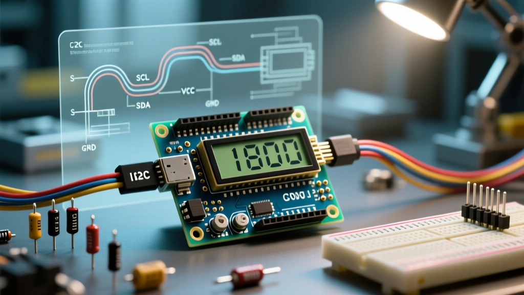
Once your base sequence is stable, consider upgrading your Arduino traffic light with modern sensor integrations. Adding an HC-SR04 ultrasonic sensor ($2.50) allows you to create a "smart intersection" that only turns green when a vehicle (or your hand) is detected in the lane. Alternatively, integrating an I2C OLED display (SSD1306) can serve as a pedestrian countdown timer. For comprehensive details on configuring digital inputs and avoiding pin conflicts, refer to the Arduino Digital Pins Foundation Guide. Understanding the underlying hardware registers and pin mappings will save you hours of debugging as your intersection grows from a single pole to a fully synchronized four-way smart grid.
Further Reading & Authoritative Sources
- SparkFun: Light Emitting Diodes (LEDs) Tutorial - Deep dive into LED physics, forward voltage, and luminosity.
- Arduino Docs: Blink Without Delay - The canonical reference for non-blocking
millis()timing. - Arduino Docs: Digital Pins - Essential reading on current limits, pull-up resistors, and pin configurations.