
Beyond Bang-Bang: Why Your Arduino Needs PID Control
If you have ever tried to maintain a precise temperature on a 3D printer hotend, stabilize a self-balancing robot, or control the speed of a DC motor under varying loads, you likely started with a simple "bang-bang" or hysteresis controller. You turn the heater on when the temperature is too low, and off when it is too high. While this works for basic home thermostats, it results in severe oscillation, overshoot, and mechanical wear in precision electronics.
Enter the PID controller for Arduino. PID (Proportional-Integral-Derivative) is a closed-loop feedback mechanism that calculates an error value as the difference between a desired setpoint (SP) and a measured process variable (PV). By applying a correction based on proportional, integral, and derivative terms, a PID controller achieves smooth, accurate, and stable control. In this guide, we will deconstruct the mathematical concepts, outline a modern 2026 hardware implementation, and provide a rigorous framework for tuning your loops.
The Anatomy of a PID Loop
To understand how a PID controller manipulates an output, we must break down its three distinct components. Think of driving a car and trying to maintain exactly 60 mph on a hilly road.
1. Proportional (P) - The Present
The Proportional term produces an output value proportional to the current error. If your speed drops to 50 mph (an error of 10), the P term presses the gas pedal proportionally. The Catch: P-only control almost always results in a steady-state error (offset). As you approach 60 mph, the error shrinks, meaning the gas pedal input shrinks. You might stabilize at 58 mph because the remaining 2 mph error doesn't generate enough output to overcome wind resistance.
2. Integral (I) - The Past
The Integral term accounts for the accumulation of past errors. It sums up the error over time. If you are stuck at 58 mph, the I term continuously grows, gradually pushing the gas pedal further down until the steady-state error is entirely eliminated. The Catch: Because it relies on accumulated history, the I term can cause overshoot. It doesn't know when to stop pushing until the error actually crosses zero and begins accumulating negative values to cancel out the positive ones.
3. Derivative (D) - The Future
The Derivative term predicts the future behavior of the error by calculating its rate of change (the slope). If you are rapidly accelerating toward 60 mph, the D term anticipates that you will overshoot and eases off the gas pedal preemptively. It acts as a damping mechanism, reducing oscillation and settling time. The Catch: Derivatives are highly sensitive to high-frequency noise. A slightly noisy sensor can cause the D term to spike, resulting in erratic actuator behavior.
Modern Hardware Architecture for PID (2026 Standard)
Let us look at a practical, high-precision thermal control loop using modern, readily available components. We will control a 12V Peltier thermoelectric cooler (TEC) to maintain a sensor at exactly 45.0°C.
- Microcontroller: Arduino Uno R4 Minima (~$20). The 32-bit Renesas RA4M1 ARM Cortex-M4 processor handles floating-point PID math and high-frequency ADC sampling vastly better than legacy 8-bit ATmega328P boards.
- Sensor: MAX6675 K-Type Thermocouple Module (~$6). Provides 0.25°C resolution via SPI, avoiding the ADC noise issues inherent in basic thermistors.
- Actuator: TEC1-12706 Peltier Module (~$12) paired with a BTS7960 43A High-Power Motor Driver (~$14). The BTS7960 accepts a 5V PWM signal from the Arduino, allowing smooth, variable DC voltage control of the Peltier.
Total BOM Cost: Approximately $52. This setup provides industrial-grade thermal stability for incubators, microfluidic heaters, or laser diode cooling rigs.
Discrete Math vs. The Arduino PID Library
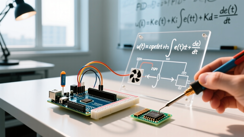
The continuous-time mathematical formula for PID is expressed as:
u(t) = Kp * e(t) + Ki * ∫e(τ)dτ + Kd * (de(t)/dt)
However, microcontrollers do not operate in continuous time; they operate in discrete millis() or micros() steps. Writing raw discrete calculus in C++ often leads to timing bugs, integral windup, and derivative kick. Instead, the industry standard is the Arduino PID Library, originally authored by Brett Beauregard. Beauregard’s seminal work on improving beginner PID implementations solved the most common edge cases that plague DIY engineers.
Core Implementation Structure
When implementing the library, your loop() function should remain free of delay() statements. The PID library relies on precise time deltas between computations.
#include <PID_v1.h>

// Define Variables we'll be connecting to
double Setpoint, Input, Output;

// Specify the links and initial tuning parameters
double Kp=2.0, Ki=0.5, Kd=1.0;
PID myPID(&Input, &Output, &Setpoint, Kp, Ki, Kd, DIRECT);

void setup() {
  Setpoint = 45.0; // Target 45.0 C
  myPID.SetMode(AUTOMATIC);
  myPID.SetOutputLimits(0, 255); // PWM limits
  myPID.SetSampleTime(100); // Compute every 100ms
}

void loop() {
  Input = readThermocouple(); // Custom SPI read function
  myPID.Compute();
  analogWrite(PWM_PIN, Output);
}
The Tuning Matrix: How Parameters Affect the System
Before attempting to tune, you must understand how adjusting each gain parameter impacts the system's step response. Refer to this matrix when diagnosing loop behavior:
| Parameter | Rise Time | Overshoot | Settling Time | Steady-State Error |
|---|---|---|---|---|
| Kp (Proportional) | Decreases | Increases | Small Change | Decreases |
| Ki (Integral) | Decreases | Increases | Increases | Eliminates |
| Kd (Derivative) | Minor Change | Decreases | Decreases | Minor Change |
Ziegler-Nichols: A Rigorous Tuning Framework
Guessing PID values (often called "twiddling") is a waste of time. For a systematic approach, use the Ziegler-Nichols Ultimate Gain method. This empirical technique forces the system to the edge of instability to find baseline constants.
- Zero out I and D: Set
Ki = 0andKd = 0. - Increase Kp: Gradually increase the Proportional gain while applying a step change to the setpoint.
- Find Ultimate Gain (Ku): Stop increasing Kp the moment the system begins to oscillate at a constant amplitude. This Kp value is your Ultimate Gain (Ku).
- Measure the Period (Tu): Measure the time it takes for one complete oscillation cycle in seconds. This is your Ultimate Period (Tu).
- Calculate Final Gains: Use the standard Z-N formulas for a PID controller:
Kp = 0.45 * KuKi = (1.2 * Kp) / TuKd = 0.075 * Kp * Tu
Note: The Arduino PID library expects Ki and Kd to be expressed in time units (seconds), not raw rates. The library handles the internal SampleTime division automatically. Ensure you input the values exactly as calculated above.
Critical Edge Cases and Failure Modes
Even with perfect math, real-world physics introduces anomalies. Here is how to handle the two most common PID failure modes in microcontroller environments.
1. Integral Windup
The Problem: If your setpoint is 100°C, but your 12V Peltier can only physically reach 80°C, the error never reaches zero. The Integral term will accumulate endlessly ("wind up"). When you finally lower the setpoint to 50°C, the massive accumulated I-term will keep the heater blasting at 100% power for minutes until the integral sum drains, causing catastrophic overshoot.
The Fix: Always use myPID.SetOutputLimits(min, max). The official PID control theory dictates that when the output saturates, the integral accumulation must be clamped. The Arduino PID library handles this clamping automatically, provided you define your physical PWM or DAC limits.
2. Derivative Kick
The Problem: The standard derivative term calculates the rate of change of the error. If you suddenly change the Setpoint from 20°C to 60°C, the error changes instantly. The derivative of an instantaneous step is mathematically infinite. This results in a massive, instantaneous spike in the Output variable, potentially damaging your actuator or tripping overcurrent protection. The Fix: Instead of taking the derivative of the error, take the derivative of the Process Variable (Measurement). Since the sensor reading cannot change instantaneously due to physical thermal or mechanical inertia, the derivative remains smooth. The Arduino PID library implements this natively; ensure you are using a modern version of the library that defaults to Derivative on Measurement.
3. Sensor Noise and 50/60Hz Mains Interference
When using high-gain Derivative terms, 50Hz or 60Hz electromagnetic interference from AC mains wiring can couple into unshielded thermocouple wires. This high-frequency noise is amplified by the D-term, causing the actuator to jitter.
The Fix: Implement a software low-pass filter (like an Exponential Moving Average) on the sensor input before passing the value to the PID Input variable. Alternatively, use shielded twisted-pair cables for analog sensors and ensure your Arduino ground is isolated from high-current motor grounds.
Summary
Implementing a PID controller for Arduino transforms erratic, oscillating hardware into a precision instrument. By understanding the distinct roles of Proportional, Integral, and Derivative terms, utilizing robust hardware like the Arduino Uno R4 and BTS7960, and applying the Ziegler-Nichols tuning method, you eliminate the guesswork from closed-loop control. Always respect physical limits to prevent integral windup, and filter your sensor data to protect your derivative calculations. With these principles, your microcontroller projects will achieve industrial-grade stability.