
The "Hello World" of Hardware: More Than Just a Blink
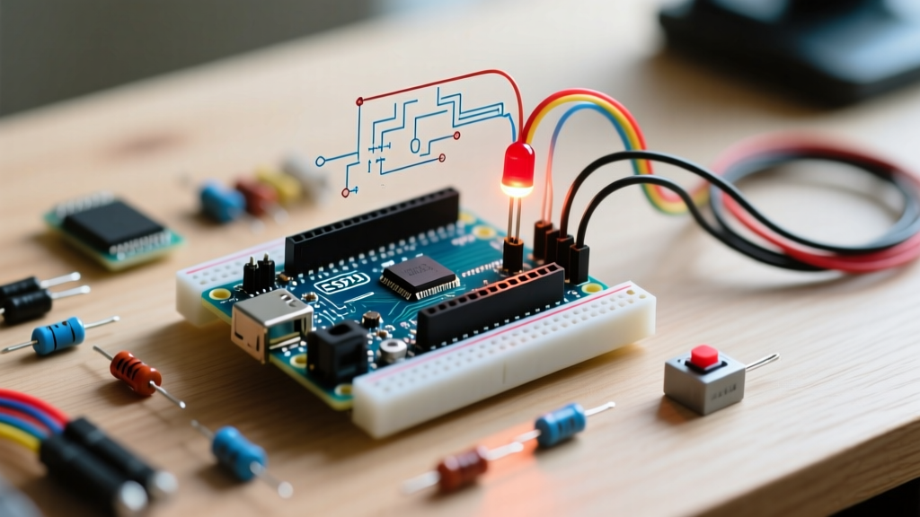
For millions of makers and engineers, the initiation into embedded systems begins with a single, universal rite of passage: blinking an LED with Arduino. While it is often dismissed as a trivial exercise, this fundamental task is actually a comprehensive diagnostic test of your entire development ecosystem. It validates the toolchain, the compiler, the bootloader, the silicon's general-purpose input/output (GPIO) registers, and the physical integrity of your breadboard circuit.
In 2026, with the maker ecosystem expanding to include advanced boards like the Arduino Uno R4 Minima and the Opta PLC, understanding the underlying physics and software architecture of a simple blink is more critical than ever. This guide moves beyond copy-paste tutorials to explain the electrical engineering principles, silicon constraints, and non-blocking logic that govern even the simplest microcontroller tasks.
The Electronics: Sizing the Current-Limiting Resistor
Light Emitting Diodes (LEDs) are non-linear semiconductor devices. Unlike resistors, they do not obey Ohm's Law linearly; instead, they possess a specific Forward Voltage ($V_f$) and will draw infinite current (until they physically fail) if connected directly to a voltage source. To safely blink an LED with Arduino, you must calculate a current-limiting resistor based on the specific chemistry of the LED die.
The Resistor Calculation Formula
The standard formula for sizing the resistor is derived from Kirchhoff's Voltage Law:
R = ($V_{source}$ - $V_f$) / $I_{target}$
For a classic Arduino Uno R3 operating at 5V logic, $V_{source}$ is 5.0V. If we are using a standard 5mm red LED with a $V_f$ of 2.0V, and we want to target a safe current ($I_{target}$) of 15mA (0.015A), the math looks like this:
R = (5.0V - 2.0V) / 0.015A = 200 Ω
Since 200 Ω is not a standard E12 series resistor value, we round up to the nearest available value: 220 Ω. Rounding up ensures the current remains slightly below our target, extending the LED's lifespan.
LED Chemistry and Resistor Sizing Chart
Different semiconductor materials emit different colors and require different forward voltages. Below is a reference table for standard 5mm through-hole LEDs when driven by a 5V Arduino GPIO pin:
| LED Color | Typical $V_f$ | Target Current | Calculated Resistance | Standard E12 Resistor |
|---|---|---|---|---|
| Red | 2.0V | 15 mA | 200 Ω | 220 Ω |
| Yellow / Green | 2.2V | 15 mA | 186 Ω | 220 Ω |
| Blue / White | 3.2V | 15 mA | 120 Ω | 120 Ω |
| Infrared (IR) | 1.3V | 20 mA | 185 Ω | 220 Ω |
Note: Always consult the manufacturer's datasheet for exact $V_f$ specifications, as high-luminosity variants can deviate significantly from these averages. For deeper component theory, refer to SparkFun's comprehensive LED guide.
Microcontroller GPIO Constraints You Must Know
A common beginner mistake is assuming all Arduino boards share the same electrical limits. When blinking an LED with Arduino, the silicon architecture dictates how much current you can safely source or sink.
ATmega328P (Uno R3 / Nano) vs. Renesas RA4M1 (Uno R4)
- Arduino Uno R3 (ATmega328P): The absolute maximum DC current per I/O pin is 40mA, but the recommended continuous operating limit is 20mA. Furthermore, the total current sourced by all Port B and Port C pins combined cannot exceed 100mA. Sinking current across all ports is capped at 150mA.
- Arduino Uno R4 Minima/WiFi (Renesas RA4M1): This modern 32-bit ARM Cortex-M4 board operates natively at 3.3V (with 5V tolerant pins). However, its GPIO current limits are much stricter. The maximum allowable current per pin is typically 8mA. If you attempt to drive a standard 20mA LED directly from an R4 pin without a transistor, you risk permanently damaging the microcontroller.
The "Pin 13" Hardware Quirk
If you use the built-in surface-mount LED on the Arduino Uno R3 (mapped to Pin 13), you are not actually driving the LED directly from the ATmega328P. According to the official Arduino Uno R3 schematics, Pin 13 is routed through an LMV358 operational amplifier acting as a unity-gain buffer. This hardware design choice prevents the LED's current draw from interfering with the SPI bus (which shares Pin 13 for SCK), ensuring stable communication with shields and SD card modules.
The Software: Blocking vs. Non-Blocking Logic
The standard "Blink" sketch provided in the Arduino IDE uses the delay() function. While functional for a single task, delay() is a blocking function. It halts the microcontroller's CPU, preventing it from reading sensors, updating displays, or processing serial data. To write professional-grade firmware, you must master non-blocking timing.
The millis() Function and Rollover Math
Instead of pausing the CPU, we track time using millis(), which returns the number of milliseconds since the board powered on. A critical edge case that separates novices from experts is handling the 50-day rollover bug. Because millis() returns an unsigned long (a 32-bit integer), it maxes out at 4,294,967,295 milliseconds (roughly 49.7 days) before rolling over to zero.
If you write your logic poorly, your LED blink sequence will freeze for 49 days when this rollover occurs. The correct, rollover-proof implementation relies on unsigned subtraction:
Correct Non-Blocking Pattern:
if (currentMillis - previousMillis >= interval) { ... }Incorrect (Rollover-Vulnerable) Pattern:
if (currentMillis >= previousMillis + interval) { ... }
For a complete breakdown of this timing architecture, review the official Arduino BlinkWithoutDelay documentation.
Advanced Edge Case: PWM and Perceived Brightness
Once you master blinking, the next logical step is fading using Pulse Width Modulation (PWM) via the analogWrite() function. However, human vision perceives brightness logarithmically, not linearly. If you linearly increase the PWM duty cycle from 0 to 255, the LED will appear to jump to full brightness almost immediately and then plateau.
To achieve a smooth, perceptually linear fade, you must apply a gamma correction curve or use an exponential mapping function in your code. Additionally, be aware that on the ATmega328P, PWM pins 5 and 6 operate at approximately 980Hz, while pins 3, 9, 10, and 11 operate at 490Hz. This discrepancy can cause visible flickering if the LED is viewed through a digital camera or used in persistence-of-vision (POV) displays.
Summary of Best Practices
- Always use a resistor: Never rely on the microcontroller's internal resistance to limit current.
- Respect silicon limits: Verify the GPIO current limits of your specific board (e.g., 20mA for R3, 8mA for R4).
- Avoid blocking delays: Use
millis()with unsigned subtraction to keep your main loop responsive. - Use transistor drivers for high power: If you need to blink high-power 1W or 3W star LEDs, use a logic-level MOSFET (like the IRLZ44N) rather than driving them from the GPIO pin.