
The Reality of Driving an Arduino VGA Monitor
Attempting to interface a microcontroller directly with a VGA display is a classic electronics rite of passage. However, the search for an Arduino VGA monitor solution often leads to immediate frustration. The original Arduino UNO (ATmega328P) operates at 16 MHz with a mere 2 KB of SRAM. Standard VESA VGA timing for 640x480 at 60Hz requires a 25.175 MHz pixel clock and substantial frame buffering—hardware realities the ATmega328P simply cannot meet without severe compromises or specialized, expensive shields.
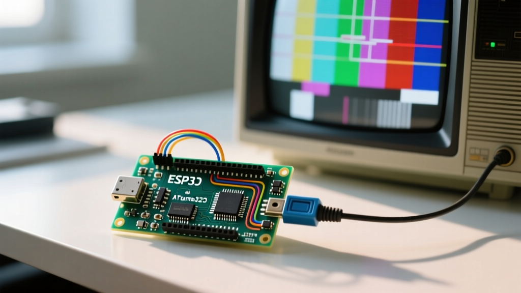
As of 2026, the maker community has almost entirely migrated to the ESP32 family for MCU-driven VGA output. The ESP32 utilizes its I2S peripheral and DMA (Direct Memory Access) to push VGA signals without bogging down the main CPU cores. Whether you are debugging a legacy ATmega328P bit-banging setup (like VGAx) or a modern ESP32 FabGL implementation, the physical layer and timing protocols remain identical. Below is a comprehensive troubleshooting matrix and fix guide for the most common VGA signal failures.
MCU VGA Capability & Troubleshooting Matrix
Before probing wires with a multimeter, ensure your microcontroller is actually capable of the resolution you are attempting to drive.
| Microcontroller | Max Practical Resolution | RAM / Buffer Limits | Output Method | Typical Hardware Cost |
|---|---|---|---|---|
| ATmega328P (UNO) | 120x160 (Grayscale/Color) | 2 KB (Requires severe tiling) | Timer Interrupts / Bit-bang | $25+ (Custom Shields) |
| ESP32 (Standard) | 640x480 @ 60Hz (8-bit color) | 520 KB SRAM (DMA backed) | I2S DMA via R2R DAC | $6 - $12 (Dev Board) |
| ESP32-S3 | 800x600 @ 60Hz (RGB565) | 512 KB + PSRAM support | LCD/RGB Peripheral / I2S | $9 - $15 (Dev Board) |
| Teensy 4.1 | 800x600+ (FlexIO) | 1 MB (Plus external PSRAM) | FlexIO Shift Registers | $35 - $45 |
Symptom 1: Monitor Displays "No Signal" or "Out of Range"
This is the most frequent failure when building an Arduino VGA monitor circuit. Modern LCD monitors are notoriously strict about VESA timing standards, unlike the forgiving CRT monitors of the past. If the horizontal sync (HSYNC) or vertical sync (VSYNC) frequencies fall outside the monitor's accepted window, the display will reject the signal entirely.
Diagnostic Steps & Fixes
- Verify VSYNC/HSYNC Polarity: Standard 640x480 @ 60Hz requires negative polarity for both HSYNC and VSYNC. If your software library is configured for positive polarity, the monitor will fail to lock onto the frame. In the FabGL ESP32 Library, ensure you are using the predefined
VGA_640x480_60Hzmodeline rather than a custom timing array. - Check the 75-Ohm Termination: VGA inputs expect a 75-ohm impedance match. If you are driving the HSYNC/VSYNC lines directly from the MCU GPIO pins without a 75-ohm pull-down resistor to ground at the VGA connector side, signal reflections will corrupt the sync pulses. Measure the resistance between the sync pins (13 and 14) and ground (pins 5, 6, 7, 8, 10) on your breakout; it should read approximately 75Ω.
- Multimeter Probe the Sync Lines: Set your multimeter to measure frequency (Hz). Probe the HSYNC line (VGA Pin 13). You should read exactly 31.46 kHz. Probe VSYNC (Pin 14); it should read 59.94 Hz. If your ESP32 is outputting 32 kHz or 55 Hz, your code's pixel clock divider is miscalculated.
Symptom 2: Severe Color Banding or "Muddy" Gradients
VGA analog RGB signals require a precise 0.7V peak-to-peak swing. Because microcontrollers output 3.3V or 5V digital logic, makers use an R2R (Resistor-to-Resistor) ladder DAC to step down the voltage and create analog color levels. Color banding almost always points to a hardware DAC failure.
The R2R Tolerance Trap
If you are using standard 5% tolerance carbon film resistors from a generic kit, your DAC will fail to produce linear voltage steps. A 5% variance on a 560Ω resistor means the actual value could be anywhere from 532Ω to 588Ω. This non-linearity destroys the gamma curve, resulting in crushed blacks, blown-out whites, and severe color banding.
- The Fix: Replace all DAC resistors with 1% tolerance metal film resistors.
- Standard 3-Bit RGB Values: For a 3-bit per channel DAC (yielding 262,144 colors), the exact resistor values connected to the GPIO pins should be 270Ω (MSB), 560Ω (Middle), and 1.2kΩ (LSB). These tie together into a single 82Ω resistor that feeds the VGA RGB pins (1, 2, and 3).
- Missing Grounds: Ensure VGA pins 5, 6, 7, 8, and 10 are all tied to your MCU's common ground. Floating grounds will cause the RGB voltages to float, resulting in wildly inaccurate colors that shift depending on the screen content.
Symptom 3: Image Tearing, Rolling, or Flickering
If the image displays but constantly rolls vertically or tears horizontally, your microcontroller is dropping DMA frames. This is highly common on the ESP32 when Wi-Fi, Bluetooth, or secondary interrupts steal CPU cycles from the VGA I2S driver.
Software & Architecture Fixes
The Espressif ESP32 architecture features dual cores. By default, the Arduino IDE runs most tasks on Core 1, while Core 0 handles the RF stack (Wi-Fi/BT). If your VGA rendering loop is competing with network interrupts, the DMA buffers will underrun.
Expert Tip: Never run heavy computational rendering (like raycasting or complex sprite math) on the same core handling your network stack. Pin your VGA drawing task explicitly to Core 1, and force Wi-Fi operations to Core 0 using
xTaskCreatePinnedToCore()in FreeRTOS.
Additionally, increase the DMA buffer descriptors. In your VGA initialization code, increasing the DMA buffer count from the default 2 to 4 or 8 provides a larger safety net against CPU latency spikes, completely eliminating micro-stutters and horizontal tearing.
Hardware Alternatives: When Breadboarding Fails
Breadboarding high-frequency VGA signals is notoriously unreliable due to parasitic capacitance and loose jumper wires. At 25 MHz, a loose Dupont wire acts as an antenna, injecting noise into the analog RGB lines. If you have verified your code and resistor values but still see "snow" or static on the screen, the physical prototyping medium is the culprit.
For reliable deployments, abandon the breadboard and use a dedicated PCB breakout. The Adafruit VGA Video Breakout or generic ESP32-VGA shield boards route the R2R ladder and 75-ohm termination resistors on a continuous ground plane, eliminating signal degradation. These boards typically cost between $8 and $15, saving hours of oscilloscope debugging and ensuring a rock-solid image on even the most pedantic modern 4K monitors utilizing legacy VGA adapters.
Summary Checklist for VGA Success
- Confirm your MCU has the RAM and clock speed for your target VESA resolution.
- Use 1% metal film resistors for all R2R DAC networks.
- Verify 75-ohm termination on HSYNC, VSYNC, R, G, and B lines.
- Measure HSYNC (31.46 kHz) and VSYNC (59.94 Hz) with a frequency counter.
- Isolate rendering tasks on dedicated CPU cores to prevent DMA underruns.