
The Ultimate Arduino Pinout Quick Reference
While the silkscreen printed on your PCB provides basic labels, it rarely tells the whole story about current limits, alternate functions, or hardware-specific quirks. Misinterpreting an Arduino pinout is the leading cause of fried microcontrollers, brownout resets, and failed I2C communications in DIY electronics. Whether you are wiring up a simple pushbutton or integrating a high-current GSM module, understanding the exact electrical characteristics of your board's headers is non-negotiable.
This FAQ and quick reference guide cuts through the fluff, providing exact current limits, frequency specifics, and common failure modes for the most popular AVR-based boards in the maker ecosystem as of 2026.
Board Comparison Matrix: Uno R3 vs. Nano V3 vs. Mega 2560
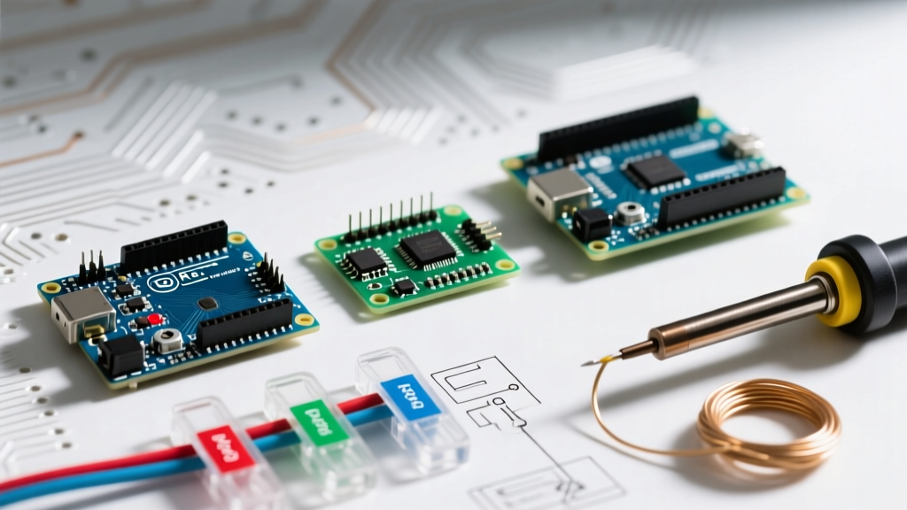
Before diving into specific pin functions, it is critical to recognize how the pinout scales across the three most common form factors. The Uno and Nano share the same underlying microcontroller, meaning their logical pinouts are identical, while the Mega offers a vastly expanded I/O footprint.
| Feature | Uno R3 / Nano V3 | Mega 2560 |
|---|---|---|
| Microcontroller | ATmega328P | ATmega2560 |
| Operating Voltage | 5V | 5V |
| Digital I/O Pins | 14 (of which 6 provide PWM) | 54 (of which 15 provide PWM) |
| Analog Input Pins | 6 (A0-A5) | 16 (A0-A15) |
| DC Current per I/O Pin | 20 mA (Recommended) | 20 mA (Recommended) |
| Hardware I2C Pins | A4 (SDA), A5 (SCL) | 20 (SDA), 21 (SCL) |
| Flash Memory | 32 KB | 256 KB |
Frequently Asked Pinout Questions
1. What are the exact current limits for the power pins?
The power header is where most catastrophic failures occur. The silkscreen simply says '5V' and '3.3V', but the underlying circuitry dictates strict limits.
- 5V Pin: This pin is tied directly to the 5V rail. If powered via USB, it is limited by the onboard PTC resettable fuse (F1) to roughly 500mA. If powered via the barrel jack (7-12V), the current is limited by the NCP1117 linear voltage regulator. While the regulator can theoretically output 1A, pulling more than 300mA to 400mA at a 12V input will cause it to overheat and trigger thermal shutdown. For high-draw components like servo motors or LED strips, always use an external buck converter (e.g., LM2596) wired directly to your power supply, sharing a common ground with the Arduino.
- 3.3V Pin: On the Uno R3, this is generated by the ATmega16U2 USB-to-serial chip's internal regulator or a secondary LDO on clone boards. It is strictly limited to 50mA (sometimes up to 150mA on specific clone implementations). Attempting to power an ESP8266 or a cellular module from this pin will instantly brownout the USB interface chip, causing your PC to fail to recognize the board.
- Vin (Voltage In): This pin connects directly to the input side of the onboard voltage regulator. You can use it to power the board with a regulated 7V-12V supply, bypassing the barrel jack. It can also be used as an output to tap into the raw voltage from the barrel jack, but it offers no regulation or protection.
2. How do PWM and Analog pins actually work?
Digital pins marked with a tilde (~) support Pulse Width Modulation via the analogWrite() function. However, not all PWM pins are created equal.
- PWM Frequencies: On the Uno and Nano, pins 3, 9, 10, and 11 operate at a default frequency of 490 Hz. Pins 5 and 6 operate at 980 Hz. If you are driving audio circuits or specific motor controllers, this 2x frequency discrepancy can cause unexpected whining or timing issues.
- Analog Inputs as Digital I/O: Pins A0 through A5 are not just for reading sensors. They map internally to digital pins D14 through D19. You can use
pinMode(A0, OUTPUT)to drive LEDs or relays, giving you 20 usable digital pins on an Uno instead of 14. - ADC Resolution: The
analogRead()function uses a 10-bit ADC, returning values from 0 to 1023. By default, it references the 5V rail. For higher precision when reading 3.3V sensors, useanalogReference(INTERNAL)to switch the reference voltage to the internal 1.1V bandgap, or feed a precise 3.3V reference into the AREF pin and useanalogReference(EXTERNAL).
3. Where are the dedicated communication pins located?
While you can use software libraries to emulate communication on any pin, hardware peripherals are tied to specific physical pins.
- UART (Serial): Pins 0 (RX) and 1 (TX) are hardwired to the ATmega328P's primary hardware serial port, which is also shared with the USB-to-serial chip. Warning: Leaving components wired to pins 0 and 1 while uploading a sketch via USB will cause upload failures and data corruption.
- I2C (Wire): On the Uno/Nano, SDA is A4 and SCL is A5. On the Mega 2560, SDA is pin 20 and SCL is pin 21. This physical pinout difference is a massive trap for makers migrating a shield from an Uno to a Mega; the shield will physically plug in, but the I2C traces will not align.
- SPI: The Uno uses pins 10 (SS), 11 (MOSI), 12 (MISO), and 13 (SCK). The Mega shifts these to 53 (SS), 51 (MOSI), 50 (MISO), and 52 (SCK). However, both boards also break out the SPI hardware lines to the 6-pin ICSP header, which remains physically identical across both form factors.
Common Pinout Mistakes and Failure Modes
Even experienced engineers make assumptions that lead to hardware damage. Here are the most frequent pinout-related failure modes we see in the field:
The 'Magic Smoke' 5V Injection: Never feed more than 5.5V directly into the '5V' pin. This pin bypasses the onboard voltage regulator entirely. Feeding 9V or 12V into the 5V pin will instantly destroy the ATmega328P and the USB interface chip. Always use the 'Vin' pin or the barrel jack for voltages above 5.5V.
Exceeding the Absolute Maximum Ratings
According to the Microchip ATmega328P datasheet, the absolute maximum DC current per I/O pin is 40mA. However, this is a stress rating, not an operating point. Running a pin continuously at 40mA degrades the silicon over time. The recommended operating current is 20mA. Furthermore, the combined current from all VCC and GND pins must not exceed 200mA. If you need to switch higher loads, use a logic-level MOSFET (like the IRLZ44N) or a dedicated relay driver board.
Missing I2C Pull-Up Resistors
The Arduino I2C pins (SDA/SCL) are open-drain. While some modern breakout boards include onboard 4.7kΩ pull-up resistors, many raw sensors do not. If your I2C scanner sketch hangs or returns garbage addresses, verify your pull-ups. You can enable the internal microcontroller pull-ups using INPUT_PULLUP, but these are roughly 30kΩ to 50kΩ—often too weak for high-speed I2C or long wire runs. Always add external 4.7kΩ resistors to the 5V rail for reliable bus communication.
Pro-Tips for Advanced Pin Management
To maximize your I/O and protect your circuits, implement these software and hardware strategies:
- Use Internal Pull-Ups: Stop wasting space and money on external 10kΩ resistors for pushbuttons. Initialize your pin with
pinMode(buttonPin, INPUT_PULLUP);and wire the button directly between the pin and GND. Read the pin asLOWwhen pressed. - Logic Level Shifting: Interfacing 3.3V sensors (like the BME280 or modern GPS modules) with 5V Arduino pins requires care. While the ATmega328P recognizes anything above 3.0V as a HIGH, feeding 5V back into a 3.3V sensor's TX line will fry it. Use a bidirectional logic level shifter (based on the BSS138 MOSFET or TXS0108E chip) for safe data translation.
- Freeing up Pins 0 and 1: If you desperately need hardware Serial but also need pins 0 and 1 for other I/O, consider using the
SoftwareSeriallibrary on pins 10 and 11 for your secondary device, or upgrade to a Mega 2560 which features three additional hardware UART ports (Serial1, Serial2, Serial3).
For further technical schematics and board-specific layouts, always consult the official Arduino Uno Rev3 documentation or the Mega 2560 hardware guide. Understanding your pinout at the silicon level is the difference between a frustrating weekend of debugging and a robust, production-ready prototype.