
Decoding the 'Wire H Arduino' Connection Dilemma
When embedded systems builders and hobbyists search for 'wire h arduino' or 'wire header Arduino' troubleshooting, they are almost universally battling the most frustrating enemy in electronics: intermittent physical connections. Whether you are prototyping with an Arduino Uno R4 WiFi or deploying a custom ATmega328P-based PCB in the field, the 2.54mm (0.1-inch) pin header is the mechanical weak point of your entire circuit.
A failing header connection doesn't just cause a blank serial monitor; it introduces phantom voltage drops, I2C bus lockups, and SPI data corruption that can take hours to debug. In this comprehensive 2026 troubleshooting guide, we will bypass generic advice and dive deep into the exact failure modes of wire-to-header connections, providing actionable, professional-grade fixes using specific tools, temperatures, and techniques.
Diagnostic Matrix: Identifying Your Header Failure
Before grabbing a soldering iron, you must accurately diagnose the failure mode. Use this matrix to isolate the root cause of your wire header Arduino issues.
| Symptom Observed | Probable Root Cause | Verification Method |
|---|---|---|
| I2C devices randomly drop off the bus; SDA/SCL errors. | High-resistance Dupont crimp or oxidized male pin. | Measure voltage drop across the wire under load (should be <20mV). |
| Arduino resets randomly when a servo or relay triggers. | Voltage sag due to undersized wire gauge or cold solder joint on VIN/5V header. | Monitor the 5V rail with an oscilloscope or fast-logging multimeter during load spikes. |
| Serial data is garbled; upload fails with 'Programmer Not Responding'. | Intermittent RX/TX header connection or lifted PCB pad near the via. | Perform a mechanical 'wiggle test' while monitoring continuity with a multimeter. |
| Sensor readings fluctuate wildly despite stable code. | Ground loop or poor GND header pin contact (fretting corrosion). | Check resistance between sensor GND and Arduino GND (must be <0.5 ohms). |
Step-by-Step Troubleshooting Workflow
Phase 1: Visual and Mechanical Inspection
Disconnect power immediately. Using a 10x magnifying loupe or a digital microscope, inspect the base of the male header pins where they meet the Arduino PCB. Look for annular ring cracks—tiny circular fractures in the solder where the pin meets the pad. Next, inspect the female Dupont or JST connectors. Are the plastic housings cracked? Is the metal terminal pushed back inside the plastic shell (a condition known as 'terminal back-out')? Gently tug on each wire; a properly crimped 28 AWG wire should withstand at least 3 lbs of pull force before failing.
Phase 2: Multimeter Continuity and Voltage Drop Testing
Standard continuity testing (the beep test) is insufficient for diagnosing high-resistance header faults because it only confirms a path exists, not that the path can carry current. Instead, perform a Voltage Drop Test.
- Power the circuit and put it under normal operating load.
- Set your multimeter to DC Millivolts (mV).
- Place the red probe on the Arduino header pin metal and the black probe on the destination component pin.
- According to official Arduino hardware troubleshooting guidelines, any reading above 50mV on a 5V logic line indicates a severe restriction in current flow, pointing directly to a failing crimp or a cold solder joint.
Fixing the Most Common Wire Header Arduino Issues
1. Re-flowing Cold Solder Joints on Pin Headers
If your Arduino clone or official board has dull, grainy, or bulbous solder joints on the headers, you are dealing with cold joints. This often happens during mass manufacturing or previous amateur repairs.
- The Fix: Do not just melt the existing solder. Apply a generous amount of Rosin Mildly Activated (RMA) flux, such as Chip Quik No-Clean flux, to the pin and pad.
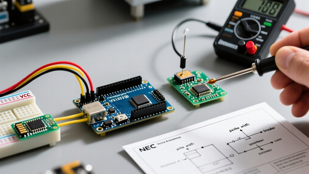
- Temperature Profile: If using 63/37 Sn/Pb (leaded) solder, set your iron (e.g., Hakko FX-888D or Pinecil V2) to 300°C. If dealing with modern RoHS-compliant lead-free SAC305 solder, increase the tip temperature to 340°C - 350°C.
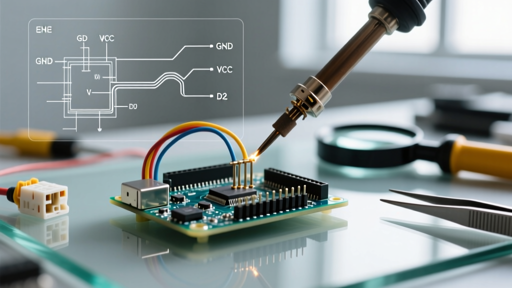
- Technique: Apply the iron tip to both the pin and the pad simultaneously for 2-3 seconds. Feed a tiny amount of fresh, high-quality flux-cored solder to act as a thermal bridge. Remove the iron and let the joint cool undisturbed for 4 seconds. The result should be a smooth, concave, and shiny fillet. For a deeper dive into proper technique, refer to the Adafruit Guide to Excellent Soldering.
2. Reseating and Re-crimping 2.54mm Dupont Connectors
Dupont wires are ubiquitous but notorious for poor crimps. If the metal tang inside the female connector isn't biting into the copper strands, you will experience micro-disconnects when the wire bends.
- Strip Length: The wire insulation strip length must be exactly 2.5mm. Too short, and the crimp bites the insulation; too long, and exposed copper risks shorting against adjacent header pins.
- The Tool: Stop using needle-nose pliers. Invest in a dedicated micro-crimper like the IWISS SN-28B or the Engineer PA-09 (typically retailing around $25-$35 in 2026). These tools feature a ratcheting mechanism that ensures the crimp reaches the exact required deformation pressure before releasing.
- Terminal Back-out Fix: If a wire pulls out of the plastic housing, use a small sewing needle or a specialized terminal extraction tool to lift the tiny plastic retaining barb inside the housing, reseat the metal crimp until it 'clicks', and verify the pull retention.
3. Repairing Lifted Pads Near Header Vias
If you accidentally pulled a wire too hard and ripped the copper pad completely off the Arduino PCB, the header pin is now mechanically unstable and electrically dead.
Expert Maker Tip: Never try to glue the pad back down and solder to it. The mechanical strength will never hold, and the thermal expansion will break the joint again within hours.
The Professional Fix: Scrape away the solder mask from the trace leading away from the lifted pad using a fiberglass scratch pen until bare copper is exposed. Tin this exposed trace. Take a piece of 30 AWG enamel-coated copper wire (magnet wire), strip the ends with a thermal stripper, and solder one end to the exposed trace and the other end directly to the header pin. Secure the repair wire with a dab of UV-curable solder mask or high-temp Kapton tape to provide strain relief.
Wire Gauge and Pitch Specifications for Arduino Headers
Using the wrong wire gauge for your specific header pitch is a primary cause of thermal failures and voltage drops. Standard Arduino headers utilize a 2.54mm (0.1') pitch. Below is the maximum safe continuous current rating for standard Dupont-style crimps at this pitch.
| Wire Gauge (AWG) | Cross-Section (mm²) | Max Continuous Current (Dupont Crimp) | Best Use Case |
|---|---|---|---|
| 28 AWG | 0.08 mm² | 1.4 Amps | I2C, SPI, UART, GPIO logic signals |
| 24 AWG | 0.20 mm² | 3.5 Amps | 5V/3.3V power rails, LED strips, small servos |
| 22 AWG | 0.32 mm² | 5.0 Amps | Main power feeds (VIN), high-current motor drivers |
Note: While the Arduino PCB traces might handle higher currents, the 2.54mm Dupont crimp terminal is the bottleneck. For currents exceeding 5A, abandon Dupont headers entirely and use screw terminals or XT60 connectors soldered directly to the board.
Preventative Best Practices for Permanent Deployments
If your project is moving from the breadboard to a permanent enclosure, standard Dupont wires on pin headers are not acceptable for long-term reliability. Vibration and thermal cycling will eventually cause fretting corrosion on the tin-plated contacts.
- Upgrade to JST Connectors: Transition to JST-XH (2.5mm pitch) or JST-SH (1.0mm pitch) connectors. As highlighted in SparkFun's hardware integration guides, JST connectors feature a positive locking mechanism that physically prevents terminal back-out and vibration-induced disconnects.
- Strain Relief: Apply a bead of neutral-cure silicone or hot melt polyamide adhesive over the wire-to-connector transition. This prevents the mechanical stress of bending the wire from transferring directly to the metal crimp or the PCB solder joint.
- Gold-Plated Headers: For harsh environments or high-humidity deployments, replace standard tin-plated Arduino headers with gold-plated equivalents. Gold does not oxidize, ensuring a low-resistance contact even after years of service.
By systematically diagnosing voltage drops, utilizing proper crimping tools, and understanding the thermal requirements of header soldering, you can permanently eliminate the 'wire h arduino' connection faults that plague embedded projects.