
The Physics and Reality of the CdS Photoresistor
Connecting a photoresistor with Arduino is a foundational milestone in embedded electronics. Often referred to as a Light Dependent Resistor (LDR) or photocell, this component changes its electrical resistance based on incident light intensity. While digital sensors like the BH1750 have taken over commercial IoT designs in 2026 due to RoHS compliance, the classic Cadmium Sulfide (CdS) photoresistor remains a staple in prototyping and education due to its ultra-low cost (typically $0.10 to $0.30 per unit) and simplicity.
However, treating an LDR as a perfect linear sensor is a common beginner mistake. CdS cells possess unique physical quirks—including spectral bias, temperature drift, and hysteresis—that must be accounted for in your circuit design and firmware.
Spectral Response: The 540nm Peak
Unlike silicon-based photodiodes that peak in the near-infrared (IR) spectrum, CdS photoresistors mimic the human eye. Their spectral response peaks at approximately 540nm (green-yellow light). This means an LDR is highly sensitive to ambient room lighting and sunlight but is practically blind to the 940nm IR light emitted by TV remote controls or IR proximity arrays. If your application requires IR detection, a photoresistor is the wrong tool; you need a dedicated phototransistor.
Component Selection: GL55 Series Comparison
The GL55 series is the industry standard for hobbyist LDRs. Selecting the right model depends on your target lux (illuminance) range.
| Model | Resistance @ 10 Lux | Dark Resistance (Min) | Best Use Case |
|---|---|---|---|
| GL5516 | 5 - 10 kΩ | 0.5 MΩ | Indoor ambient light tracking |
| GL5528 | 10 - 20 kΩ | 1.0 MΩ | General purpose day/night detection |
| GL5537 | 20 - 30 kΩ | 2.0 MΩ | Low-light / dusk-activated triggers |
The Voltage Divider: Bridging Resistance and ADC
Microcontrollers cannot read resistance directly; they only measure voltage. To use a photoresistor with Arduino, you must convert the variable resistance into a variable voltage using a voltage divider circuit. As explained in SparkFun's Voltage Divider Tutorial, this requires placing a fixed resistor in series with the LDR.
The Voltage Divider Formula:
Vout = Vin × [ Rfixed / (RLDR + Rfixed) ]
Choosing the Fixed Resistor
The value of your fixed resistor dictates the sensitivity curve of your sensor. A standard 10kΩ resistor is the universal default, providing a balanced voltage swing for the GL5528 in typical indoor lighting. However, if you are building a solar tracker (high lux), dropping the fixed resistor to 1kΩ shifts the sensitive range toward brighter light. Conversely, for a night-sky camera trigger, bumping the fixed resistor to 100kΩ maximizes resolution in the dark.
Step-by-Step Wiring Guide
Follow this exact topology to ensure clean analog readings and avoid floating pin noise:
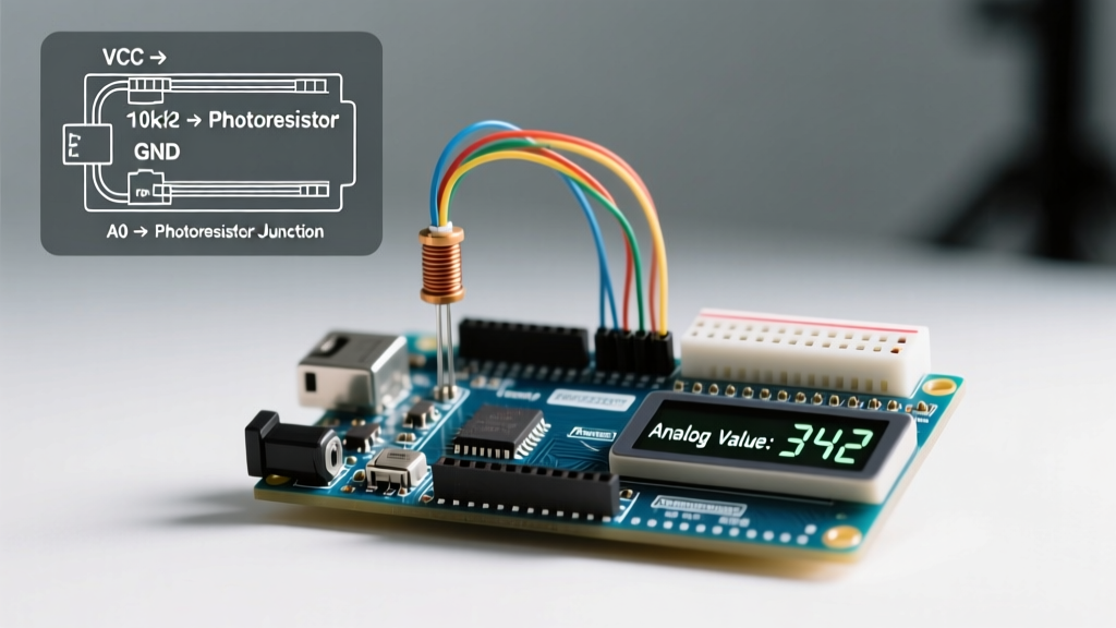
- Power Rail: Connect the Arduino 5V pin to one leg of the photoresistor. (LDRs are non-polarized, so orientation does not matter).
- Sense Node: Connect the other leg of the photoresistor to Arduino Analog Pin A0.
- Fixed Resistor: Connect one leg of a 10kΩ resistor to the same A0 node.
- Ground: Connect the other leg of the 10kΩ resistor to the Arduino GND pin.
- Stabilization (Optional but Recommended): Place a 0.1µF ceramic capacitor between A0 and GND to filter out high-frequency electromagnetic interference (EMI) from nearby switching power supplies.
Arduino Code: Reading and Smoothing Analog Data
Raw analogRead() values from an LDR circuit are notoriously noisy due to the high impedance of the voltage divider and the 10-bit SAR ADC's sensitivity to VCC ripple. According to the official Arduino analogRead() documentation, the ADC can take up to 100 microseconds to stabilize. Furthermore, environmental light flicker (like 50Hz/60Hz AC mains lighting) can introduce rapid fluctuations.
Below is a production-ready sketch that implements an Exponential Moving Average (EMA) filter to smooth out ADC jitter without introducing the lag associated with simple delay loops.
// Photoresistor with Arduino - Smoothed EMA Filter
const int ldrPin = A0;
float smoothedValue = 512.0; // Initialize to mid-range
const float alpha = 0.1; // Smoothing factor (0.0 to 1.0). Lower = smoother but slower.

void setup() {
  Serial.begin(115200);
  analogReference(DEFAULT); // Ensure 5V reference on standard boards
}

void loop() {
  int rawReading = analogRead(ldrPin);

  // Apply Exponential Moving Average
  smoothedValue = (alpha * rawReading) + ((1.0 - alpha) * smoothedValue);

  // Map the smoothed 10-bit ADC value (0-1023) to a 0-100% light scale
  // Note: Invert the map if your voltage divider topology yields high voltage in the dark
  int lightPercentage = map((int)smoothedValue, 0, 1023, 0, 100);

  Serial.print("Raw: ");
  Serial.print(rawReading);
  Serial.print(" | Smoothed: ");
  Serial.print(smoothedValue);
  Serial.print(" | Light: ");
  Serial.print(lightPercentage);
  Serial.println("%");

  delay(50); // 20Hz sampling rate
}
Real-World Failure Modes and Edge Cases
When deploying a photoresistor with Arduino in real-world environments, be prepared for these physical limitations:
- Temperature Coefficient Drift: CdS cells exhibit a negative temperature coefficient. As ambient temperature rises, the resistance drops, mimicking an increase in light. In outdoor enclosures that heat up to 50°C in the sun, your sensor will report "brighter" light even if clouds pass over. Compensate for this in firmware using a co-located thermistor (e.g., NTC 10k B3950).
- The Memory Effect (Hysteresis): If an LDR is kept in total darkness for hours and is suddenly exposed to bright light, its resistance will drop rapidly, but it will take several seconds to "settle" at its true illuminated resistance. This latency makes CdS cells unsuitable for high-speed optical encoding or tachometers.
- RoHS and Supply Chain Shifts: Cadmium is a heavy metal restricted under the EU's RoHS directive. While hobbyist markets still carry them via Adafruit and similar vendors, commercial manufacturing in 2026 has largely abandoned CdS in favor of digital ambient light sensors.
Sensor Comparison Matrix: LDR vs. Modern Alternatives
Is a CdS photoresistor the right choice for your specific project? Use this matrix to decide.
| Feature | CdS Photoresistor (GL5528) | Silicon Photodiode (BPW34) | Digital Lux Sensor (BH1750) |
|---|---|---|---|
| Output Type | Analog (Resistance) | Analog (Current) | Digital (I2C) |
| Resolution | Depends on ADC & Resistor | Extremely High | 16-bit (1-65535 lux) |
| Response Time | Slow (20ms - 50ms) | Ultra-fast (nanoseconds) | Moderate (120ms integration) |
| IR Sensitivity | Very Low (Peaks at 540nm) | High (Peaks at 900nm) | Filtered (Mimics human eye) |
| Approx. Cost (2026) | $0.15 | $0.45 | $1.20 |
| Best Application | Simple night-lights, basic education | IR remotes, laser tripwires | Smart home screens, plant grow lights |
Summary
Mastering the photoresistor with Arduino requires moving beyond basic tutorials. By understanding the spectral limitations of Cadmium Sulfide, properly sizing your voltage divider fixed resistor for your specific lux range, and implementing software-based EMA filtering to tame ADC noise, you can extract highly reliable environmental light data. While digital sensors are the future of commercial IoT, the analog LDR remains an invaluable, low-cost tool for rapid prototyping and foundational electronics education.