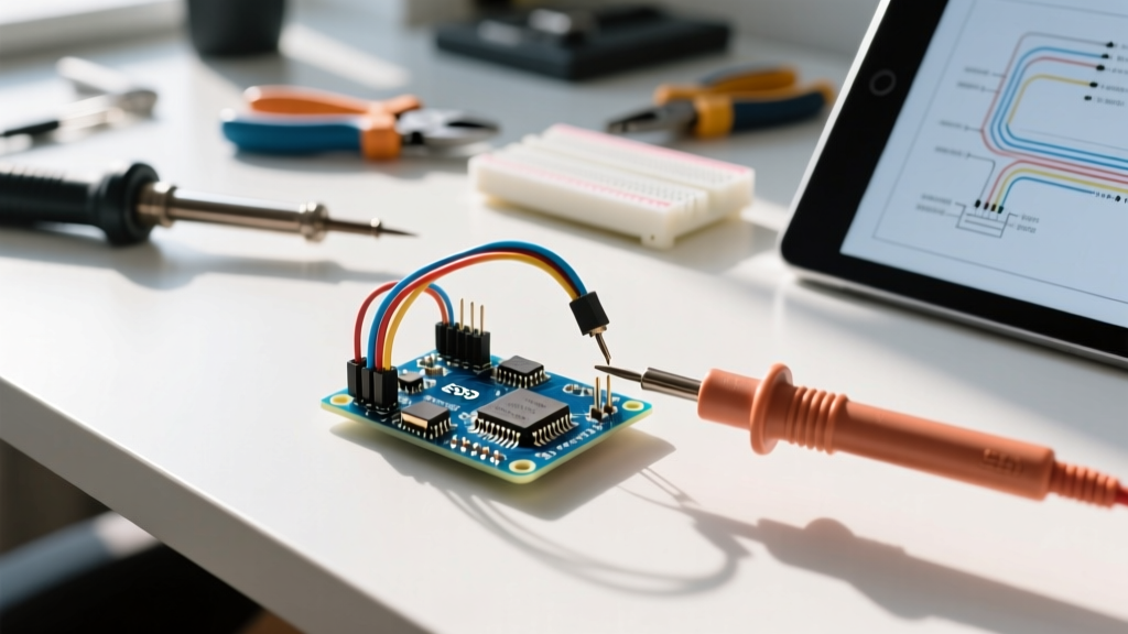

The "Ghost in the Machine" Phenomenon
Every maker has experienced it: you upload a perfectly verified sketch to your Arduino Uno or Nano, only to be greeted by random serial garbage, unexplained brownout resets, or I2C sensors that mysteriously drop off the bus. You spend hours rewriting code, swapping microcontrollers, and questioning your logic, only to find the real culprit is a $0.02 piece of wire. In 2026, the maker market is saturated with ultra-cheap, mass-produced jumper wires for Arduino projects, and their failure rates are higher than ever. Diagnosing hardware-level signal integrity issues requires shifting your mindset from software logic to physical electrical properties.
Expert Insight: A standard digital multimeter continuity test is a liar. It pushes less than 1mA of current through the wire. A failing jumper wire with a corroded or loose internal crimp will easily pass a continuity test, but will cause a massive voltage drop when your servo motor or OLED display attempts to draw 200mA.
The Anatomy of a Failing Dupont Connector
Most jumper wires for Arduino prototyping utilize 2.54mm pitch Dupont-style connectors. The failure rarely occurs in the copper strand itself; it occurs at the crimp joint or the retention tang.
Common Physical Failure Modes
- The Pushed-Back Tang: Inside the female plastic housing is a small metal spring tab (the tang) meant to grip the male header pin. If manufactured poorly or inserted incorrectly, this tang gets pushed backward. The connector slides onto the pin, but makes contact only via friction against the plastic housing, resulting in micro-vibrations breaking the circuit.
- Copper-Clad Aluminum (CCA) Strands: To cut costs, many cheap wire kits use CCA instead of pure stranded copper. CCA has roughly 40% higher electrical resistance and is highly brittle. Repeated bending causes the aluminum core to snap inside the PVC insulation, creating an intermittent open circuit.
- Insulation Crimp Interference: In poorly crimped wires, the PVC insulation gets caught inside the metal crimp barrel alongside the copper strands. This creates a high-resistance junction that generates heat and voltage drop under load.
Diagnostic Matrix: Symptom vs. Wire Fault
When troubleshooting, map your sketch's erratic behavior to the specific electrical domain of the failing wire. Use this diagnostic matrix to isolate the issue:
| Observed Symptom | Suspected Domain | Actual Wire Fault | Definitive Test |
|---|---|---|---|
I2C devices fail to initialize or return 0xFF | Data (SDA/SCL) | High resistance on GND wire shifting logic LOW threshold, or bus capacitance exceeded. | Measure voltage drop on GND wire relative to MCU GND under load. |
| Analog sensors (e.g., A0) show random jitter (±15 ADC steps) | Signal / Reference | Crosstalk from adjacent digital wires, or poor shielding on the analog jumper. | Oscilloscope AC-coupled probe on the analog pin; look for 16MHz clock noise. |
| ATmega328P resets when a servo moves | Power (VCC/GND) | Severe voltage drop on 28 AWG VCC wire triggering the 2.7V Brown-out Detection (BOD). | Measure VCC at the servo's end while stalled; look for >0.5V drop. |
| SPI SD Card throws CRC errors or fails to mount | High-Speed Data | MISO/MOSI wires are too long (>15cm) or bundled, causing signal reflection and crosstalk. | Shorten wires to <10cm and separate them; verify termination. |
Step-by-Step Voltage Drop Diagnosis Protocol
To properly diagnose faulty jumper wires for Arduino circuits, you must test them under real-world operating conditions. You will need a reliable True-RMS multimeter (like a Fluke 117 or Brymen BM235) and your loaded circuit.
- Establish the Baseline: Power your Arduino via USB or a regulated bench supply. Measure the 5V pin directly at the Arduino header. Record this value (e.g., 4.98V).
- Measure Under Load: Connect your peripheral (e.g., an LED matrix or motor driver) using the suspect jumper wires. Force the peripheral into its highest current-draw state.
- Probe the Destination: Place your multimeter's red probe on the 5V pin at the peripheral's header, and the black probe on the peripheral's GND pin.
- Calculate the Drop: Subtract the destination voltage from the baseline. According to DigiKey's wire gauge resistance charts, a standard 24 AWG copper wire has a resistance of about 25.7 milliohms per foot. A 6-inch wire should drop less than 20mV at 500mA. If you measure a drop greater than 150mV, the wire or crimp is defective and must be discarded.
Signal Integrity: I2C and SPI Edge Cases
Digital communication protocols are highly sensitive to the physical characteristics of your jumper wires. The I2C specification strictly limits total bus capacitance to 400 pF. As noted in SparkFun's I2C Tutorial, long, unshielded jumper wires can introduce 15 to 20 pF of capacitance per foot. If you use 12-inch jumper wires to route SDA and SCL to a remote sensor, you are adding nearly 40 pF per line. Bundle those wires tightly with power lines, and parasitic capacitance and crosstalk will round off the sharp square-wave edges of your I2C clock, causing the peripheral to miscount bits and lock up the bus.
Similarly, SPI buses running at 8MHz or higher (common with TFT displays and SD card modules) suffer from signal reflection if the jumper wires are too long or lack a solid, low-inductance ground return path. Always route a dedicated GND jumper wire immediately adjacent to your SPI MOSI and SCK lines to provide a tight return loop, minimizing inductive ringing.
Upgrading Your Wire Arsenal: Specs That Matter
Stop relying on the rainbow ribbon cables included in cheap starter kits. For mission-critical prototyping and permanent breadboard layouts, upgrade to wires that meet professional electrical standards. As detailed in SparkFun's Working with Wire guide, understanding American Wire Gauge (AWG) and insulation material is vital for reliable projects.
Material and Gauge Recommendations
- Wire Gauge: Abandon standard 28 AWG wires for power distribution. Upgrade to 26 AWG or 24 AWG for all VCC and GND lines. The lower the AWG number, the thicker the copper strand, drastically reducing resistance and voltage drop.
- Insulation: Switch from rigid PVC to Silicone insulation. Silicone wires (like those produced by Adafruit or Pololu) are highly flexible, resist melting when soldered, and don't suffer from the "memory effect" that causes PVC wires to stiffen and pull loose from breadboards over time.
- Connector Plating: Look for gold-flashed Dupont connectors rather than tin-plated ones. Gold resists oxidation, ensuring a low-contact-resistance connection even in humid environments or after months of sitting on a shelf.
Pro-Tip: Custom Crimping for Reliability
For the ultimate reliability, build your own custom-length jumper wires using a high-quality ratcheting crimp tool (such as the Pololu Crimp Tool for 2.54mm Housings). A proper ratcheting tool ensures the copper crimp barrel is cold-welded to the wire strands, while the insulation crimp barrel securely grips the silicone jacket. This completely eliminates the "insulation inside the crimp" failure mode and guarantees a gas-tight connection that will outlast the Arduino itself.
Final Troubleshooting Checklist
Before you blame the microcontroller or rewrite your C++ library, run through this physical layer checklist:
- Wiggle test: Gently flex the wire near the crimp joint while monitoring serial output or an oscilloscope trace.
- Verify tang tension: Use a fine sewing needle to gently pry the internal metal tang forward if a female connector feels loose on a male header.
- Check routing: Ensure high-speed data lines (SPI/I2C) are not wrapped around stepper motor wires or relays, which inject massive EMI spikes into the signal lines.
- Replace the ground: When in doubt, swap the GND wire first. A flawed ground reference corrupts every single signal on the board simultaneously.
By treating jumper wires for Arduino not as mere accessories, but as critical transmission lines, you will eliminate hours of phantom debugging and build hardware that operates flawlessly in the real world.