
The Reality of Motor Control Failures
When a robotic chassis refuses to move or a conveyor belt stutters unpredictably, the immediate instinct is to blame the code or assume the microcontroller is fried. However, in the realm of embedded systems, the vast majority of motor board Arduino setup failures stem from electrical architecture flaws, not software bugs. As we navigate the 2026 maker landscape, where 3.3V architectures like the ESP32-S3 and Raspberry Pi Pico have largely eclipsed the traditional 5V Arduino Uno for new designs, legacy motor drivers are frequently mismatched with modern logic levels.
This diagnostic guide bypasses generic troubleshooting advice and dives deep into the specific failure modes of popular H-bridge modules. We will cover ground loop-induced logic resets, BJT versus MOSFET voltage drop traps, and the notorious PWM timer collisions that silently disable motor control pins.
The 80% Rule: Power Architecture and Ground Loops
Approximately 80% of all motor board Arduino errors originate in the power delivery network. Motors are highly inductive loads that draw massive stall currents—often 5 to 10 times their nominal running current. When a motor starts, this current spike creates voltage sag and electromagnetic interference (EMI) that can corrupt microcontroller logic.
The Common Ground Imperative
A frequent and catastrophic error is failing to establish a common ground between the microcontroller, the motor driver, and the high-current power supply. If you are powering an L298N motor board with a 12V LiPo battery and your Arduino via USB, the GND pin of the L298N must be physically wired to the GND pin of the Arduino.
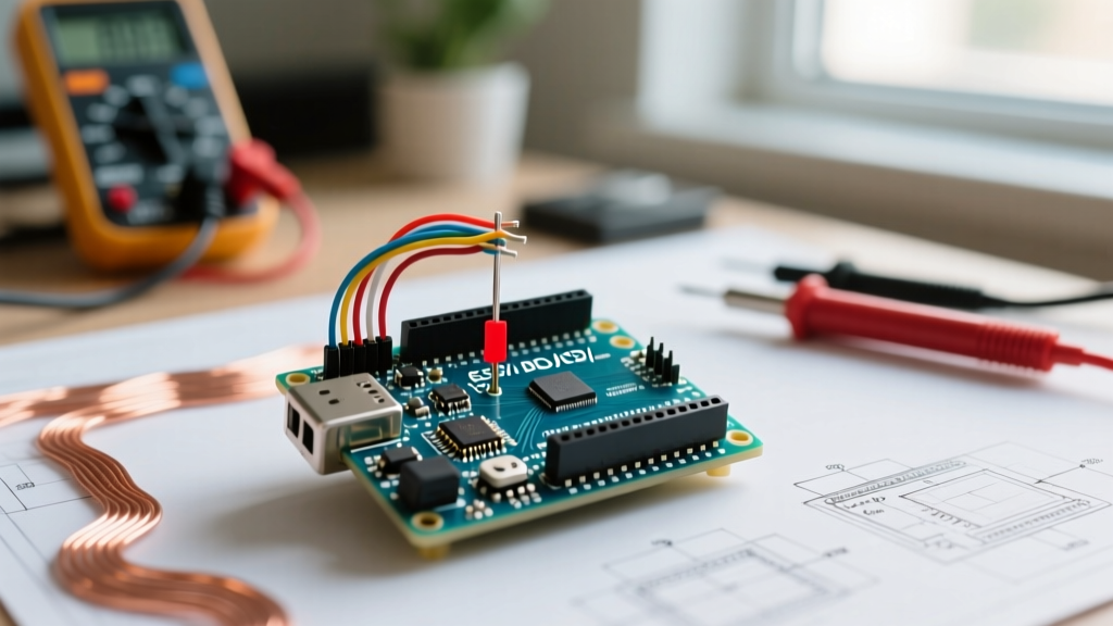
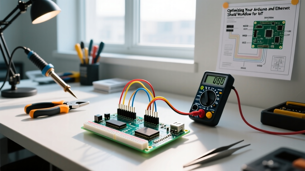
Pro Diagnostic Tip: Do not just assume your ground wires are intact. Use a digital multimeter set to DC voltage. Place the red probe on the Arduino's GND pin and the black probe on the motor driver's logic GND pin while the motors are actively running. If you read a voltage difference greater than 0.1V, your ground wire is too thin, too long, or suffers from a cold solder joint. Upgrade to at least 18 AWG silicone wire for power grounds.
Voltage Drop and the L298N Trap
The L298N remains a staple in beginner kits due to its low price point ($4 to $8 for clones in 2026), but it utilizes an outdated Bipolar Junction Transistor (BJT) Darlington pair topology. This design inherently suffers from a massive voltage drop—typically 1.8V to 3.2V depending on the current draw. If you supply 5V to the VCC of an L298N, your motors will only receive 2V to 3V, resulting in severe stalling and the false diagnosis of a 'broken' motor board. For 5V to 6V motor applications, you must abandon the L298N and transition to a MOSFET-based driver.
Hardware Diagnostic Matrix: Choosing the Right Architecture
Understanding the physical limitations of your specific motor board is critical for accurate error diagnosis. Below is a comparative matrix of the most common drivers encountered in Arduino ecosystems.
| Driver IC / Module | Topology | Voltage Drop / Rds(on) | Logic VCC Tolerance | Typical 2026 Price |
|---|---|---|---|---|
| L298N (Red Module) | BJT Darlington | 2.0V - 3.2V (High) | 5V (Marginal at 3.3V) | $4.00 - $8.00 |
| TB6612FNG (Pololu) | MOSFET | ~0.5V (Low Rds(on)) | 2.7V - 5.5V | $5.00 - $10.00 |
| DRV8871 (TI Breakout) | MOSFET | ~0.4V (Very Low) | 2.2V - 5.5V | $3.50 - $6.00 |
| Arduino Motor Shield R3 | L298P (BJT) | 2.0V - 3.0V | 5V (Native Uno Shield) | $15.00 - $25.00 |
For modern, high-efficiency designs, the Texas Instruments DRV8871 and the Pololu TB6612FNG are the industry standards, completely eliminating the BJT voltage drop errors inherent to the L298N.
Logic Level Mismatches in Modern MCUs
As the maker community shifts toward 3.3V microcontrollers like the ESP32 and Arduino Nano 33 IoT, logic level mismatches have become a primary source of motor board Arduino errors.
The 3.3V vs 5V Threshold Problem
The L298N datasheet specifies a minimum high-level input voltage (VIH) of 2.3V, which theoretically means a 3.3V ESP32 GPIO pin should trigger it. However, in real-world scenarios with EMI from brushed motors, the noise margin is destroyed. A 3.3V signal often fails to reliably switch the internal BJT optocouplers or logic gates on cheap clone L298N boards, leading to erratic motor spinning or complete unresponsiveness.
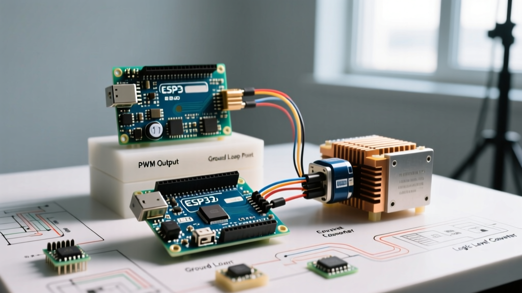
The Fix: If you must use an L298N with a 3.3V MCU, you need a logic level shifter (like a 4-channel BSS138 module) or a simple NPN transistor (e.g., 2N2222) circuit to pull the 5V logic line to ground. Alternatively, bypass the L298N entirely and use a TB6612FNG, which natively supports logic thresholds down to 2.7V, making it perfectly compatible with 3.3V architectures without level shifting.
PWM Timer Collisions and Frequency Errors
Motor speed is controlled via Pulse Width Modulation (PWM). However, the Arduino `analogWrite()` function relies on hardware timers that are easily hijacked by popular libraries, resulting in silent motor failures where the pin outputs a static HIGH or LOW instead of a PWM wave.
The Servo Library Conflict
If your project involves both a robotic arm (servos) and a drive base (DC motors via a motor board), you will likely use the standard Arduino `
If your motor board's ENA or ENB pins are wired to Pins 9 or 10, calling `myServo.attach()` will instantly disable PWM on those pins. The motor will suddenly jump to 100% speed or stop entirely, depending on how the driver interprets a static HIGH signal. According to the official Arduino analogWrite reference, you must route motor PWM signals to Pins 3, 5, 6, or 11 (controlled by Timer0 and Timer2) when using the Servo library on an Uno.
PWM Frequency and Audible Whine
Standard Arduino PWM operates at roughly 490Hz or 980Hz. This falls squarely within the human hearing range, causing brushed motors and the ceramic capacitors on motor boards to emit a high-pitched, annoying whine. Furthermore, some advanced motor drivers require higher frequencies to properly filter the current. You can alter the PWM frequency by manipulating the Timer registers directly. For example, changing the prescaler on Timer1 (Pins 9 and 10) to run at 31.25kHz pushes the frequency above human hearing and smooths out motor commutation, drastically reducing EMI noise that often causes I2C sensor errors on the same bus.
Inductive Kickback and Flyback Diode Failures
When a motor is spinning, it acts as an inductor. When the H-bridge suddenly cuts power or reverses direction, the collapsing magnetic field generates a massive reverse voltage spike (inductive kickback). This spike can easily exceed 50V, instantly punching through the MOSFETs or BJTs on your motor board and permanently shorting the driver.
While most commercial motor boards include onboard flyback diodes, they are frequently undersized or too slow. The standard 1N4007 diode has a reverse recovery time that is far too slow for high-frequency PWM applications. If you are experiencing repeated, inexplicable motor board deaths, the root cause is likely inadequate flyback protection.
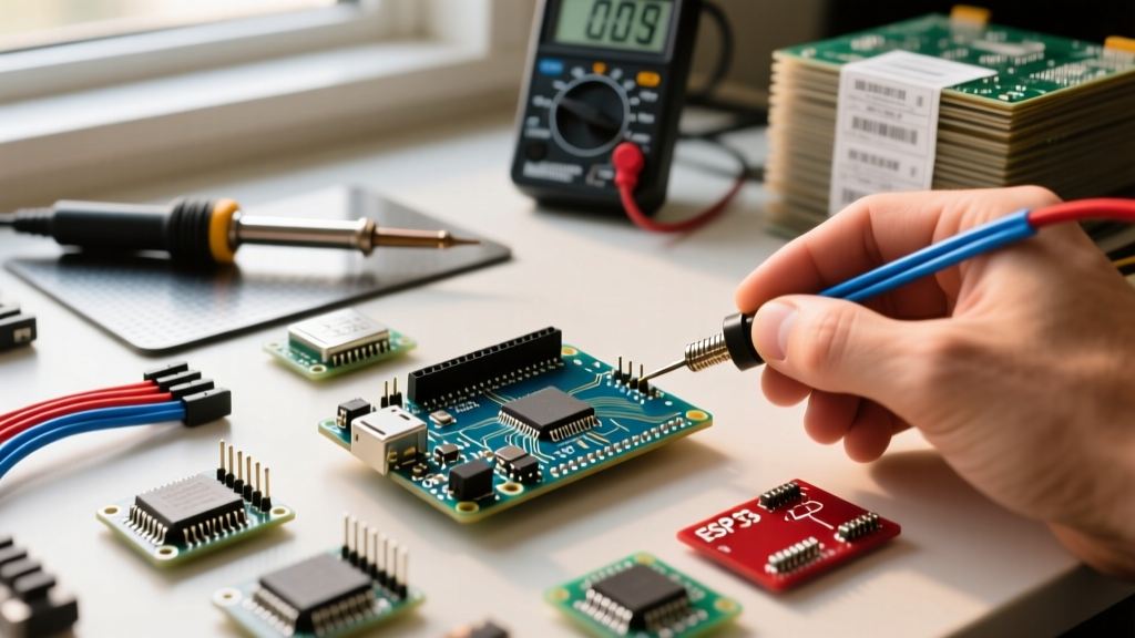
The Actionable Fix: Solder Schottky diodes (such as the 1N5819 or SS14) directly across the motor terminals, as close to the motor casing as physically possible. Schottky diodes have near-zero reverse recovery time and a lower forward voltage drop, safely clamping the inductive spike before it travels back through the wiring harness and destroys your motor driver IC.
Step-by-Step Multimeter Diagnosis Protocol
When your motor board Arduino setup fails, follow this exact diagnostic sequence before rewriting a single line of code:
- Verify VM / VCC: Measure the voltage at the motor power supply terminals on the driver board under load. If it drops below the motor's rated voltage by more than 15%, your power supply is browning out.
- Verify Logic VCC: Measure the logic pin (VCC or 5V) on the driver. Ensure it reads a stable 4.8V to 5.2V (or 3.3V for modern drivers).
- Check Enable Pins: Use a multimeter to confirm that the Enable (ENA/ENB) pins are receiving either a steady 5V (for full speed) or a PWM signal. (Note: A standard multimeter will read the average DC voltage of a PWM signal; a 50% duty cycle will read ~2.5V).
- Isolate the MCU: Disconnect the motor board from the Arduino. Manually jumper the IN1 and IN2 pins to 5V and GND. If the motor spins, the hardware is fine, and your error is strictly in the software, pin mapping, or timer conflicts.
By systematically isolating the power delivery, logic thresholds, and timer architectures, you can eliminate the guesswork from motor control. Upgrading from legacy BJT drivers to modern MOSFET boards and respecting the electrical realities of inductive loads will yield robust, professional-grade motion control in your embedded projects.