
Introduction to Photoresistor-Based Lighting Control
Integrating a light-dependent resistor (LDR) with a microcontroller is a foundational skill in embedded systems. A photo resistor LED Arduino configuration allows you to build responsive, auto-dimming circuits or automatic night-lights that react to ambient illumination. While commercial smart lighting relies on complex I2C digital sensors like the BH1750, the analog cadmium sulfide (CdS) photoresistor remains a staple in 2026 for DIY prototyping due to its low cost, simplicity, and high sensitivity to visible light spectrums.
However, simply wiring an LDR to an analog pin rarely yields professional results. Makers frequently encounter ADC noise, twilight flickering, and non-linear dimming curves. This configuration guide dives deep into the hardware topology, firmware mapping, and advanced software hysteresis required to build a robust, flicker-free auto-dimming LED circuit.
Component Selection and 2026 Pricing Matrix
Selecting the right LDR and pull-down resistor is critical. The resistance of a CdS cell drops non-linearly as light intensity increases. Below is a matrix of standard components, their typical 2026 market pricing for hobbyist quantities, and their specific use cases.
| Component | Model / Spec | Approx. Cost (USD) | Key Characteristics |
|---|---|---|---|
| Photoresistor (LDR) | GL5528 | $0.15 | 10-20kΩ @ 10 Lux. Best for indoor room lighting. |
| Photoresistor (LDR) | GL5516 | $0.12 | 5-10kΩ @ 10 Lux. Higher sensitivity, good for outdoor dusk detection. |
| Pull-Down Resistor | 10kΩ Carbon Film | $0.02 | ±5% tolerance. Standard for 5V logic voltage dividers. |
| Microcontroller | Arduino Uno R4 Minima | $27.50 | Features a 14-bit ADC (vs 10-bit on R3), providing 4x the resolution for fine light gradients. |
| Output LED | 5mm Diffused (Warm White) | $0.08 | 20mA forward current, 2.2V forward voltage. |
Hardware Configuration: The Voltage Divider Topology
Microcontrollers cannot read resistance directly; they read voltage. Therefore, you must configure the LDR in a voltage divider circuit. This topology pairs the variable resistance of the LDR with a fixed pull-down resistor to output a variable voltage between 0V and 5V (or 3.3V, depending on your board's logic level).
Step-by-Step Wiring Guide
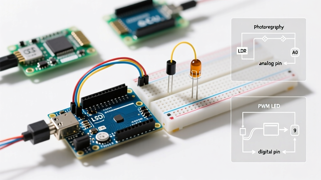
- Power the LDR: Connect one leg of the GL5528 photoresistor to the Arduino's 5V pin.
- Create the Divider Node: Connect the other leg of the LDR to one leg of the 10kΩ fixed resistor. This junction is your signal node.
- Ground the Fixed Resistor: Connect the free leg of the 10kΩ resistor to the Arduino GND pin.
- Route the Analog Signal: Connect a jumper wire from the signal node (the junction between the LDR and the 10kΩ resistor) to Analog Pin A0.
- Configure the LED Output: Connect the anode (long leg) of the LED to Digital Pin 9 (a hardware PWM-capable pin) via a 220Ω current-limiting resistor. Connect the cathode (short leg) to GND.
Expert Insight on Resistor Sizing: The fixed resistor value should ideally match the LDR's resistance at the midpoint of your target lighting environment. If you are building an outdoor streetlight trigger (detecting twilight), a 10kΩ resistor might be too low; swapping to a 100kΩ pull-down resistor will shift the voltage divider's sensitivity curve to trigger accurately at lower lux levels.
Firmware Configuration: Reading and Mapping Analog Values
With the hardware configured, the next step is reading the analog input and mapping it to a Pulse Width Modulation (PWM) output. If you are using the classic Arduino Uno R3, the ADC is 10-bit (0-1023). If you have upgraded to the Uno R4, you can configure the ADC to 14-bit (0-16383) for vastly superior dimming smoothness.
Below is the baseline configuration sketch for a 10-bit ADC system that inversely maps light levels to LED brightness (i.e., darker room = brighter LED).
// Photo Resistor LED Arduino Baseline Configuration
const int ldrPin = A0;
const int ledPin = 9;

void setup() {
  Serial.begin(115200);
  pinMode(ledPin, OUTPUT);
  // Note: analogReadResolution(14) can be added here for Uno R4 boards
}

void loop() {
  int rawLightLevel = analogRead(ldrPin);

  // Invert and map the 10-bit ADC value (0-1023) to PWM range (0-255)
  // High light = High raw value = Low PWM output
  int ledBrightness = map(rawLightLevel, 0, 1023, 255, 0);

  // Constrain to prevent overflow anomalies
  ledBrightness = constrain(ledBrightness, 0, 255);

  analogWrite(ledPin, ledBrightness);

  // Debugging output
  Serial.print("Raw ADC: ");
  Serial.print(rawLightLevel);
  Serial.print(" | PWM Out: ");
  Serial.println(ledBrightness);

  delay(50); // 50ms polling rate prevents serial buffer flooding
}
Advanced Configuration: Implementing Hysteresis to Eliminate Flicker
The most common failure mode in a basic photo resistor LED Arduino setup is twilight flicker. When ambient light hovers exactly around your trigger threshold (e.g., a cloud passing over the sun, or a car headlight sweeping across the room), the ADC value oscillates. This causes the LED to rapidly strobe on and off.
To solve this, professional firmware implements software hysteresis (a Schmitt trigger logic). Instead of a single threshold, you define an upper and lower bound.
Hysteresis Logic Implementation
- Turn ON Threshold: The LED only turns on when the light level drops below 300.
- Turn OFF Threshold: The LED only turns off when the light level rises above 350.
- Deadband: The 50-point gap (300 to 350) is the hysteresis band. While the sensor reads values in this band, the LED maintains its previous state, entirely eliminating rapid toggling.
int thresholdOn = 300;
int thresholdOff = 350;
bool ledState = false;

void loop() {
  int rawLight = analogRead(A0);

  if (rawLight < thresholdOn && !ledState) {
    ledState = true;
    digitalWrite(ledPin, HIGH);
  }
  else if (rawLight > thresholdOff && ledState) {
    ledState = false;
    digitalWrite(ledPin, LOW);
  }
  delay(100);
}
Troubleshooting Edge Cases and Hardware Failure Modes
Even with perfect code, physical layer issues can derail your circuit. Use this diagnostic matrix to resolve anomalous behaviors.
1. Floating or Erratic Analog Readings
Symptom: Serial monitor shows random values jumping from 0 to 1023 even when the LDR is covered.
Cause: A broken ground connection on the 10kΩ pull-down resistor, leaving the A0 pin floating and acting as an antenna for 50/60Hz mains EMI.
Fix: Verify continuity from the fixed resistor to the Arduino GND rail using a multimeter. Ensure breadboard contact springs are not fatigued.
2. LED Fails to Dim Smoothly (Stair-Stepping)
Symptom: The LED visibly steps through brightness levels rather than fading smoothly.
Cause: Human eyes perceive light logarithmically, but PWM outputs linearly. Additionally, a 10-bit ADC only provides 1024 steps, which can cause noticeable banding in low-light conditions.
Fix: Apply a gamma correction curve in your firmware to map linear ADC steps to logarithmic PWM outputs. Alternatively, upgrade to an Arduino Uno R4 and utilize the 14-bit ADC for 16,384 discrete steps.
3. Circuit Triggers in Complete Darkness
Symptom: The LED turns off when the room is pitch black.
Cause: You have wired the LDR and fixed resistor in reverse order. If the LDR is connected to GND and the fixed resistor to 5V, the voltage at A0 will approach 0V in the dark (high LDR resistance) and 5V in the light.
Fix: Swap the physical positions of the LDR and the 10kΩ resistor, or invert your software mapping logic.
Conclusion
Mastering the photo resistor LED Arduino configuration requires moving beyond basic tutorials. By carefully selecting your pull-down resistor to match your target lux environment, utilizing hardware PWM for smooth dimming, and implementing software hysteresis to create a deadband, you transform a jittery science fair project into a reliable, commercial-grade ambient lighting controller. Whether you are building a smart terrarium canopy or an automated porch light, these foundational topologies will ensure consistent, flicker-free operation.