
The Shift from Guesswork to Systematic Power Profiling
Designing battery-operated IoT nodes or remote environmental sensors requires a rigorous approach to energy management. Relying on a standard multimeter to measure Arduino power consumption is a flawed workflow; multimeters average out microsecond wake-up spikes and miss transient current draws that silently drain batteries. To achieve multi-year battery life, makers and engineers must adopt a systematic workflow: profile the baseline, optimize firmware sleep states, implement hardware power gating, and select ultra-low quiescent regulators.
In 2026, the ecosystem for low-power microcontrollers is more robust than ever, but the fundamental physics of battery depletion remain unforgiving. A single floating pin or an overlooked voltage regulator can turn a theoretically five-year sensor node into a two-week paperweight.
Phase 1: High-Resolution Current Profiling
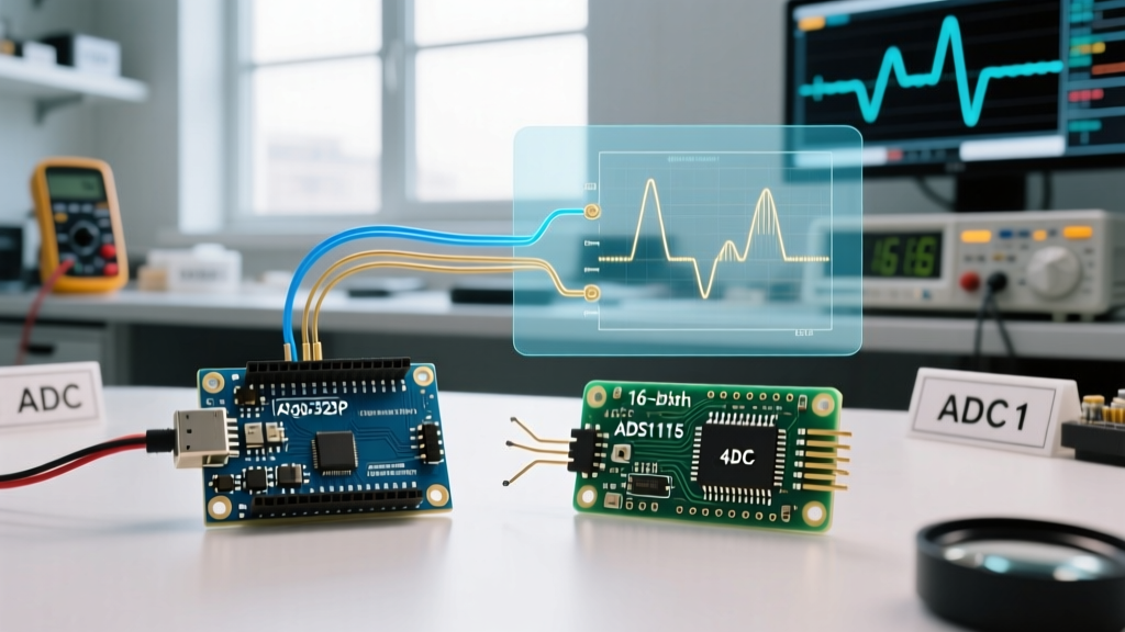
Before writing a single line of sleep-code, you must establish an accurate baseline. Standard digital multimeters sample too slowly to capture the 5ms to 50ms wake-up bursts typical of RF transmissions.
Recommended Profiling Tools
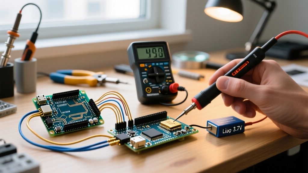
- Nordic Power Profiler Kit II (PPK2): Priced around $92, this is the industry standard for maker and prosumer workflows. It samples at 100 kHz with a dynamic range from 200 nA to 1A, allowing you to visualize the exact current signature of an ESP32 waking up, connecting to WiFi, transmitting, and returning to deep sleep.
- Qoitech Otii Arc Pro: At approximately $650, this is geared toward commercial engineering teams. It integrates seamlessly into CI/CD pipelines, allowing automated power regression testing whenever firmware is updated.
- Brymen BM786 Multimeter: If you must use a multimeter, use one with a dedicated micro-amp range and data-logging capabilities, though it will still miss high-frequency transient spikes.
For authoritative guidance on setting up hardware profiling, refer to the Nordic Semiconductor PPK2 documentation, which details proper shunt resistor placement and ground-loop avoidance.
Phase 2: Hardware Selection Matrix
Not all "Arduino-compatible" boards are created equal. Development boards often include onboard LEDs, USB-to-Serial converters, and linear regulators that make deep sleep impossible without physical modification. Below is a comparison of popular architectures for low-power workflows.
| Microcontroller / Board | Active Current (Approx.) | Deep Sleep / Power Down | Workflow Suitability |
|---|---|---|---|
| Arduino Nano 33 IoT (SAMD21) | ~15 mA | ~1.5 mA (Standby) | Poor for coin-cell; requires board mod to cut USB chip. |
| ESP32-C3 SuperMini | ~25 mA (WiFi TX) | ~5 µA | Excellent for WiFi; requires careful RTC memory management. |
| Seeed XIAO nRF52840 | ~5 mA (BLE TX) | ~2 µA (System OFF) | Best-in-class for BLE; native LiPo charging management. |
| Barebones ATmega328P (8MHz) | ~4 mA | ~0.1 µA | Ultimate for ultra-low power, but lacks native wireless. |
Phase 3: Firmware-Level Sleep State Optimization
Putting a microcontroller to sleep involves more than calling a delay function. You must systematically disable internal peripherals that consume leakage current.
AVR Architecture (ATmega328P)
When using the LowPower.h library or native AVR sleep modes, the most critical edge case is the Brown-Out Detector (BOD). By default, the BOD remains active during sleep to prevent erratic behavior if voltage drops, but it draws approximately 20 µA. In a low-power workflow, you must disable the BOD via software or by programming the fuse bits. As detailed in the official Arduino low-power guide, disabling the BOD and ADC drops the ATmega328P sleep current from ~20 µA down to ~0.1 µA.
ESP32 Architecture
For ESP32 variants, deep sleep shuts down the CPU and most RAM, but you can retain the Ultra-Low Power (ULP) coprocessor and RTC memory. According to the Espressif Sleep Modes API reference, retaining RTC fast memory costs roughly 1 µA per 8KB block. Only store the exact variables required for wake-up state tracking to minimize this overhead.
Phase 4: Peripheral Power Gating and the I2C Backfeed Trap
A common workflow failure occurs when engineers put the MCU to sleep but leave sensors powered on. A BME280 sensor in standby still draws ~1 µA, and a DS3231 RTC draws ~2 µA. To achieve true zero-peripheral draw, you must use a P-channel MOSFET (like the SI2301, costing ~$0.08 in bulk) or a dedicated load switch to physically cut VCC to the sensors.
Critical Edge Case: I2C Backfeeding
If you cut power to an I2C sensor via a MOSFET, but the MCU's SDA and SCL pins remain HIGH (due to internal or external pull-up resistors), current will flow backward through the sensor's internal ESD protection diodes. This "backfeed" can draw 1 to 3 mA, completely defeating the purpose of power gating and potentially degrading the sensor over time.
The Workflow Fix: Before triggering the MOSFET to cut sensor power, reconfigure the MCU's SDA and SCL pins to OUTPUT LOW. Alternatively, use an I2C bus isolator like the PCA9306, which features dedicated enable pins and prevents backfeeding natively.
Phase 5: Voltage Regulator Quiescent Current (Iq)
The voltage regulator is the silent killer of battery-operated projects. Cheap Arduino clones use the AMS1117-3.3 linear regulator. While fine for USB-powered prototyping, the AMS1117 has a quiescent current (Iq) of 5 mA to 10 mA. Even if your MCU draws 0 µA in sleep, the regulator will drain a 2000 mAh 18650 battery in less than three weeks.
Regulator Upgrade Path
- MCP1700-3302E: An ultra-low Iq LDO. It draws only 1.6 µA of quiescent current and supports up to 250 mA. Ideal for coin-cell and small LiPo applications.
- TPS62740: A high-efficiency buck converter from Texas Instruments. It features an Iq of just 360 nA (0.36 µA) and is optimized for battery-powered IoT nodes drawing less than 200 mA.
Real-World Case Study: The 5-Year CR2032 Node
Let us apply this workflow to a theoretical environmental sensor powered by a standard CR2032 coin cell (nominal capacity: 225 mAh). The target lifespan is 5 years (43,800 hours).
The Power Budget Math:
Total Capacity: 225 mAh
Target Lifespan: 43,800 Hours
Maximum Average Current Draw: 225 / 43800 = 5.13 µAIf the node wakes up every 15 minutes (900 seconds), transmits for 50ms at 15 mA, the duty cycle is 0.0055%. The average current consumed by the wake-up burst is roughly 0.83 µA. This leaves a strict budget of 4.3 µA for the MCU sleep state, the voltage regulator Iq, and any always-on peripherals.
To achieve this, the workflow dictates using a barebones ATmega328P (0.1 µA sleep), an MCP1700 regulator (1.6 µA Iq), and a hardware RTC interrupt. Total sleep draw: 1.7 µA. Combined with the wake-up average, the total node draw sits at ~2.5 µA, safely under the 5.13 µA budget, guaranteeing a 5+ year lifespan.
Summary Checklist for Your Next Build
- Profile First: Use a PPK2 to measure actual transient spikes, not just static sleep states.
- Strip the Board: Remove power LEDs, USB-Serial chips (CH340/CP2102), and inefficient LDOs from development boards.
- Disable BOD: Turn off the Brown-Out Detector in AVR firmware before entering
SLEEP_MODE_PWR_DOWN. - Gate Peripherals: Use MOSFETs to cut sensor power, and explicitly pull I2C lines LOW to prevent diode backfeeding.
- Audit the Regulator: Ensure your voltage regulator's Iq is measured in nano-amps or low micro-amps, not milliamps.
By treating power management as a structured engineering workflow rather than an afterthought, you can reliably deploy Arduino-based nodes that run for years on a single battery, eliminating maintenance overhead and enabling truly remote sensing applications.