
The Reality of Timing in Microcontroller Design
When makers first transition from basic LED blinking to complex robotics or data logging, they inevitably hit a wall: the delay() function. Blocking the main loop for timing is a fatal flaw in embedded systems. While the millis() function offers a non-blocking software alternative, it still relies on the CPU continuously polling the clock. For true precision, zero-jitter execution, and CPU offloading, you must configure hardware timers. This guide dissects timer Arduino configurations, contrasting raw ATmega328P register manipulation with modern ESP32 APIs and software libraries.
ATmega328P Timer Architecture: Know Your Hardware
The standard Arduino Uno and Nano utilize the Microchip ATmega328P microcontroller. This chip contains three distinct hardware timers. Understanding their default assignments is critical; overriding the wrong timer will silently break core Arduino functions.
| Timer | Resolution | Default Arduino Usage | Safe to Override? |
|---|---|---|---|
| Timer0 | 8-bit | millis(), delay(), micros() |
No (Breaks core timing) |
| Timer1 | 16-bit | Servo library, PWM pins 9 & 10 |
Yes (With caution) |
| Timer2 | 8-bit | tone(), PWM pins 3 & 11 |
Yes (With caution) |
If your project requires high-resolution pulse-width modulation (PWM) or precision periodic interrupts without disturbing the system clock, Timer1 is your primary target. Because it is a 16-bit timer, it can count up to 65,535 before overflowing, offering vastly superior granularity compared to the 8-bit timers.
Step-by-Step: Configuring Timer1 for Precision Interrupts
Let us configure Timer1 on a 16MHz Arduino Uno to trigger an Interrupt Service Routine (ISR) exactly every 10 milliseconds (100Hz). We will use Clear Timer on Compare Match (CTC) mode.
The Mathematics of Prescalers
The ATmega328P runs at 16,000,000 Hz. To slow this down to a usable counting speed, we apply a prescaler. Available prescalers for Timer1 are 1, 8, 64, 256, and 1024.
- Target Frequency: 100 Hz (0.01s period)
- Prescaler Selection: 256
- Timer Tick Rate: 16,000,000 / 256 = 62,500 Hz
- Compare Match Value (OCR1A): (62,500 / 100) - 1 = 624
Register Configuration Code
Instead of relying on bulky third-party libraries, writing directly to the Timer/Counter Control Registers (TCCR) yields the most efficient machine code. According to the official Microchip ATmega328P datasheet, the following bit-shifting operations configure the hardware:
void setup() {
  cli(); // Disable global interrupts during setup

  // Reset Timer1 control registers
  TCCR1A = 0;
  TCCR1B = 0;

  // Set compare match register to 624
  OCR1A = 624;

  // Turn on CTC mode (WGM12 bit in TCCR1B)
  TCCR1B |= (1 << WGM12);

  // Set CS12 and CS10 bits for 256 prescaler
  TCCR1B |= (1 << CS12) | (1 << CS10);

  // Enable timer compare interrupt (OCIE1A bit in TIMSK1)
  TIMSK1 |= (1 << OCIE1A);

  sei(); // Re-enable global interrupts
}
Once configured, the hardware autonomously counts to 624, triggers the ISR(TIMER1_COMPA_vect) block, and resets to zero. The main CPU loop remains entirely free to handle sensor polling or serial communications.
Modern Alternatives: ESP32 and SAMD21 Timer APIs
The embedded landscape in 2026 extends far beyond 8-bit AVR chips. Modern 32-bit microcontrollers abstract raw register manipulation into robust Hardware Abstraction Layers (HAL).
ESP32 Hardware Timers
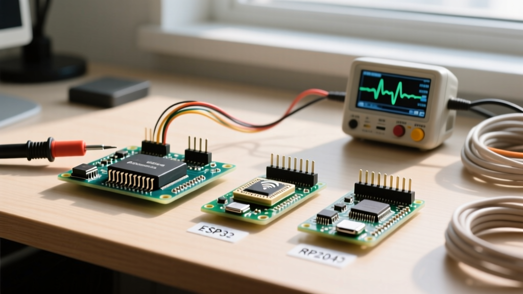
The ESP32-WROOM-32 (and newer ESP32-C3 variants, which typically cost between $3 and $5 on volume markets) features four 64-bit general-purpose timers. The ESP-IDF and Arduino cores utilize the hw_timer_t API. Rather than calculating prescalers manually, you define the clock divider and alarm values in microseconds.
Referencing the Espressif ESP-Timer API documentation, the ESP32 handles the complex routing of the Advanced Peripheral Bus (APB) clock to the timer groups automatically, eliminating the prescaler guesswork required on the ATmega328P.
SAMD21 (Arduino Zero) TCC vs. TC
The SAMD21G18A chip differentiates between TC (Timer/Counter for basic intervals) and TCC (Timer/Counter for Control, optimized for complex motor-control PWM). When configuring a timer Arduino setup on a Zero, you must instantiate the correct generic clock (GCLK) multiplexer to feed the timer, a step that trips up many developers migrating from AVR.
Software Timers: When Libraries and Millis() Win
Hardware timers are not always the correct tool. If your timing requirements tolerate a jitter of 1 to 4 milliseconds, software-based approaches are vastly easier to maintain and debug.
Expert Rule of Thumb: If the timing event involves I2C, SPI, or heavy Serial printing, do NOT use a hardware ISR. Use millis() in the main loop instead.
The Ticker and TimerOne Libraries
For ESP8266 and ESP32 boards, the Ticker library provides a lightweight software timer that executes callbacks without locking the CPU. For AVR boards, the TimerOne library wraps the complex register math shown earlier into a simple Timer1.initialize(10000) function call. While TimerOne consumes a few extra bytes of flash memory, it prevents syntax errors in bit-shifting operations that can brick a sketch's timing logic.
Critical Edge Cases and Failure Modes
Configuring timers is only half the battle. The most common point of failure in advanced MCU projects occurs inside the Interrupt Service Routine (ISR). Avoid these three catastrophic edge cases:
- The I2C Deadlock: The Arduino
Wire.hlibrary relies on its own interrupts to handle I2C bus states. If your Timer1 ISR triggers while the main loop is reading an I2C sensor, and your ISR attempts to callWire.requestFrom(), the system will deadlock permanently. Always set avolatile booleanflag in the ISR and handle the I2C read in the mainloop(). - Missing the Volatile Keyword: Variables shared between the ISR and the main loop must be declared as
volatile. Without this, the GCC compiler will cache the variable in a CPU register during optimization, meaning the main loop will never see the updates made by the hardware timer. - ISR Execution Overrun: An ISR must execute faster than the timer interval. If your 10ms timer ISR contains
delay(15)or complex floating-point math, the next interrupt will be missed or queued, destroying the timing accuracy and potentially overflowing the interrupt vector table.
Summary: Choosing Your Timing Strategy
Mastering the timer Arduino ecosystem requires matching the tool to the tolerance. Use millis() for UI debouncing and non-blocking LED fades. Use the TimerOne library for rapid prototyping of 16-bit AVR interrupts. Reserve raw TCCR register manipulation and ESP32 hardware timer APIs for high-speed data acquisition, software-defined PWM, and strict real-time control loops where microsecond jitter is unacceptable.