
The Hidden Cost of Naive Arduino LED and Button Implementations
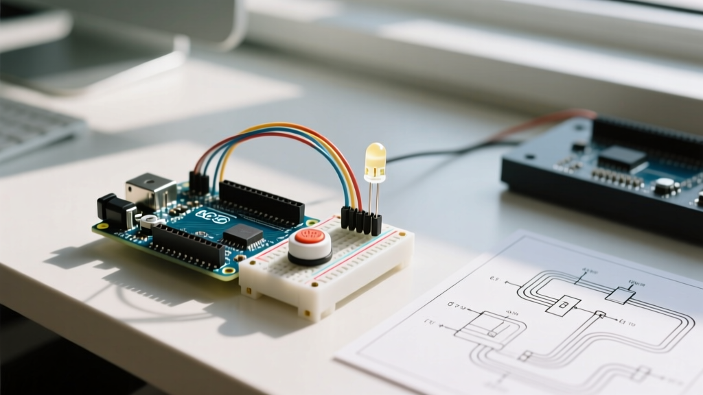
Every maker starts with the same foundational project: an Arduino LED and button circuit. While toggling an LED via a tactile switch seems trivial, transitioning this basic concept into a reliable, production-ready workflow exposes severe engineering pitfalls. Naive implementations relying on digitalRead() inside a blocking loop() inevitably fail in real-world environments due to mechanical switch bounce, floating pin states, and electromagnetic interference (EMI).
When optimizing your microcontroller workflow, treating the Arduino LED and button paradigm as a complex input system rather than a simple binary check saves hours of debugging. According to Jack Ganssle's definitive guide to debouncing, mechanical switches can exhibit contact bounce lasting anywhere from 1.5ms to over 50ms. If your MCU polls the pin at a high frequency, a single physical press can register as a dozen distinct state changes, completely ruining user experience in applications like menu navigation or precise step-counting.
Hardware vs. Software Debouncing: A Workflow Decision Matrix
Optimizing your development workflow requires making the right architectural choices early. Should you handle switch bounce in silicon or in code? The decision impacts your Bill of Materials (BOM), PCB real estate, and CPU overhead. Below is a decision matrix to streamline your component selection process in 2026.
| Debouncing Method | BOM Cost (per unit) | Code Overhead | Best Workflow Use Case |
|---|---|---|---|
| Software (Bounce2 Library) | $0.00 | Low (Non-blocking) | Rapid prototyping, multi-button arrays |
| Hardware (RC Low-Pass Filter) | ~$0.05 | None | Simple interrupts, low-power sleep modes |
| Hardware (74HC14 Schmitt Trigger) | ~$0.35 | None | High-EMI environments, long wire runs |
| Software (ezButton Library) | $0.00 | Medium (Polling) | Beginner workflows, basic state toggles |
For most modern MCU workflows, the Bounce2 library remains the gold standard for software debouncing. It utilizes an object-oriented approach that abstracts the millis() timing logic, allowing you to instantiate multiple button objects without cluttering your main loop with timing variables. However, if your Arduino is spending most of its time in a low-power sleep state, waking via interrupt requires a hardware RC filter or a Schmitt trigger to prevent bounce from triggering multiple wake-up cycles.
Architecting the Non-Blocking State Machine
The most common workflow bottleneck occurs when developers use delay() to manage LED blinking or button debounce timing. This blocks the CPU, preventing the MCU from reading sensors or managing communications. To optimize your Arduino LED and button workflow, you must adopt a finite state machine (FSM) architecture driven by millis().
Implementing the Bounce2 FSM Pattern
Instead of checking if a button is currently HIGH or LOW, optimize your logic to detect transitions. The fell() and rose() methods in Bounce2 are critical for this. Here is the structural workflow for a robust toggle mechanism:
- Initialization: Configure the pin using
INPUT_PULLUPto leverage the ATmega328P's internal 20kΩ-50kΩ pull-up resistors. This eliminates the need for external resistors on short wire runs. - Attachment: Bind the Bounce object to the pin with a 10ms debounce interval (sufficient for most Omron B3F and C&K PTS645 tactile switches).
- State Evaluation: In the
loop(), calldebouncer.update()and check fordebouncer.fell()to trigger the LED state change exactly once per physical press.
Expert Workflow Tip: Never usedelay()for LED feedback. If you need an LED to blink for 500ms after a button press, store themillis()timestamp of the press in a variable and evaluate the delta in the main loop. This keeps your button input latency under 1ms, ensuring a snappy, professional user interface.
Rapid Prototyping to Production: Component Selection
When moving your Arduino LED and button circuit from a breadboard to a custom PCB or perfboard, component selection dictates your assembly speed and long-term reliability. In 2026, the market offers highly optimized tactile switches that minimize mechanical failure modes.
Switch Selection and Pricing
The C&K PTS645 series (approx. $0.12–$0.18 in volume) is a staple for maker workflows due to its crisp tactile feedback and consistent 5ms bounce time. For harsher environments or high-actuation applications, the Omron B3F series ($0.20–$0.30) offers superior dust resistance and a longer mechanical lifespan of up to 3 million cycles. Avoid unbranded 6x6mm tactile switches from bulk marketplace bins; their inconsistent leaf-spring tension leads to variable bounce times that will break your software debounce thresholds.
Managing Parasitic Capacitance and EMI
If your button is located more than 30cm away from the microcontroller via a ribbon cable or twisted pair, the internal pull-up resistor is no longer sufficient. The wire acts as an antenna, and parasitic capacitance slows the rise time of the signal, causing phantom triggers. According to All About Circuits hardware filtering analysis, you must lower the pull-up resistance to 4.7kΩ or even 1kΩ to provide a stronger current source that overcomes the cable's capacitance, ensuring sharp logic-level transitions.
Troubleshooting Common Edge Cases
Even with optimized code and quality components, specific edge cases can derail your Arduino LED and button project. Address these during your testing workflow:
- Phantom Presses on Power-Up: If your LED toggles randomly when the board is first powered or reset, your input pin is floating before the MCU initializes the internal pull-ups. Fix this by adding a physical 10kΩ external pull-up resistor directly at the switch terminals.
- Ground Loop Interference: When driving high-current LED strips (like WS2812B or 12V PWM strips) alongside low-voltage button inputs, the sudden current draw can cause ground bounce. This shifts the MCU's ground reference, tricking the
digitalRead()into seeing a LOW state. Always route high-current ground returns separately from logic-level grounds, tying them together at a single star point. - Switch Contact Oxidation: In high-humidity environments, cheap switch contacts oxidize, increasing contact resistance. This can prevent the internal pull-up from pulling the pin fully HIGH. Use gold-plated contact switches or implement a software 'pull-down and read' diagnostic routine during startup to verify switch health.
Frequently Asked Questions
Can I use the same pin for an LED and a Button?
While technically possible using Charlieplexing or specialized analog threshold tricks, it is a poor workflow optimization. It requires complex timing to switch the pin mode between OUTPUT and INPUT, which introduces severe latency and flickering. Always dedicate separate pins unless you are severely constrained on I/O, in which case consider an I2C I/O expander like the MCP23017 ($1.20) to offload the button matrix.
Why does my button work in the serial monitor but fail to toggle the LED?
This is a classic symptom of a blocking code structure. If your LED control logic relies on delay(), the MCU is blind to button presses during the delay window. The serial print might catch the press because it's buffered, but the state machine misses the transition. Refactor to a millis()-based non-blocking architecture as outlined in the official Arduino Debounce documentation.
Is hardware debouncing necessary for modern 32-bit MCUs like the ESP32?
No. Modern 32-bit MCUs running at 240MHz have more than enough processing overhead to handle software debouncing for dozens of inputs simultaneously. Hardware debouncing on an ESP32 is generally a waste of BOM cost and PCB space unless you are utilizing deep-sleep wake-up interrupts, where the CPU is completely powered down and cannot run software polling routines.