
The Evolution of Arduino Wi-Fi Workflows
If you are still wiring ESP-01 modules to an Arduino Uno via breadboards and wrestling with AT-command firmware, your development workflow is bottlenecked by a decade-old paradigm. Understanding how to connect Wi-Fi to Arduino in 2026 is no longer just about making a hardware connection; it is about optimizing the entire firmware iteration loop. Modern IoT development demands native TCP/IP stacks, Over-The-Air (OTA) update capabilities, and low-latency telemetry pipelines. This guide bypasses legacy tutorials and focuses strictly on high-velocity, production-ready workflows for connecting Arduino ecosystems to Wi-Fi networks.
Hardware Selection Matrix: Choosing the Right Node
Before writing a single line of code, you must select the right silicon. The 'shield' era of stacking a $40 Wi-Fi module atop a $20 microcontroller is dead. Today, workflow optimization dictates using System-on-Chip (SoC) architectures or native bridge coprocessors.
| Hardware Platform | Core Architecture | Wi-Fi Standard | Avg. Cost (2026) | Workflow Velocity |
|---|---|---|---|---|
| Arduino Uno R4 WiFi | ARM Cortex-M4 + ESP32-S3 Coprocessor | 802.11 b/g/n (2.4GHz) | $27.50 | High (Native IDE integration) |
| ESP32-DevKitC-V4 | Xtensa Dual-Core 32-bit LX6 | 802.11 b/g/n + Bluetooth 4.2 | $6.00 - $8.00 | Maximum (PlatformIO / OTA native) |
| ESP8266 NodeMCU V3 | Tensilica L106 32-bit RISC | 802.11 b/g/n (2.4GHz) | $4.50 | Medium (Memory constraints) |
| Legacy WiFi101 Shield | ATmega328P + WINC1500 | 802.11 b/g/n | $35.00+ | Low (SPI bottleneck, no OTA) |
Workflow 1: The Arduino Uno R4 WiFi (The Native Bridge)
For makers who require the exact pinout and 5V logic tolerance of the classic Uno form factor but need modern connectivity, the Arduino Uno R4 WiFi is the optimal choice. It utilizes an ESP32-S3 minipcie module acting as a coprocessor, communicating with the primary RA4M1 ARM chip via a high-speed serial bridge.
Optimizing the Uno R4 Setup
- Library Selection: Do not use the legacy
WiFi.horWiFiNINA.hlibraries. You must include#include <WiFiS3.h>. This library is specifically optimized for the ESP32-S3 coprocessor architecture. - Network Scanning: The S3 coprocessor handles the heavy lifting. Use
WiFi.scanNetworks()asynchronously to prevent blocking the main ARM Cortex-M4 loop, ensuring your sensor polling rates remain stable. - LED Matrix Bonus: The R4 WiFi includes a 12x8 LED matrix. Route your Wi-Fi connection status (e.g., DHCP acquired, MQTT connected) to this matrix via the
Arduino_LED_Matrix.hlibrary to eliminate the need for external status LEDs during prototyping.
For comprehensive setup instructions and board definitions, always refer to the Arduino Official Documentation Hub, ensuring your IDE boards manager is updated to the latest UNO R4 core.
Workflow 2: Native ESP32 with PlatformIO (Maximum Velocity)
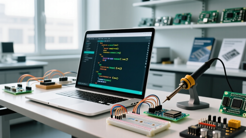
If your project does not strictly require the Uno form factor, migrating to a native ESP32-DevKitC-V4 is the single greatest workflow optimization you can make. By abandoning the Arduino IDE 2.x in favor of PlatformIO (via VS Code), you unlock automated dependency management, multi-environment builds, and significantly faster compilation times.
PlatformIO Configuration for Wi-Fi
Instead of manually downloading ZIP libraries, define your Wi-Fi and MQTT dependencies in the platformio.ini file:
[env:esp32dev]
platform = espressif32
board = esp32dev
framework = arduino
lib_deps =
    knolleary/PubSubClient@^2.8
    bblanchon/ArduinoJson@^6.21.3
monitor_speed = 115200
This configuration pulls the exact versions of the MQTT and JSON parsing libraries required for your project, ensuring your build is reproducible across different machines—a critical step for professional IoT workflows.
Expert Insight: The ESP32's Wi-Fi stack is deeply integrated into the FreeRTOS operating system. Never placeWiFi.begin()or network request functions inside a tightloop()without yielding. UsevTaskDelay()or asynchronous callbacks to prevent the watchdog timer (WDT) from resetting the board due to network stack starvation.
Optimizing Data Telemetry: HTTP REST vs. MQTT
Once the physical and logical Wi-Fi connection is established, the next workflow bottleneck is data transmission. Many beginners default to HTTP POST requests to a REST API. This is inefficient for real-time IoT nodes.
- HTTP REST: Requires a full TCP handshake, TLS negotiation (if using HTTPS), and header parsing for every single payload. An ESP32 sending a 50-byte JSON payload via HTTPS can draw upwards of 300mA and take 1.5 to 3 seconds per transaction.
- MQTT: Maintains a persistent, lightweight TCP connection. Using the
PubSubClientlibrary, an ESP32 can publish a 50-byte payload to a local Mosquitto broker in under 15 milliseconds, drawing significantly less peak current. This frees up the MCU to return to deep sleep faster, optimizing battery-powered workflows.
Cutting the Cord: Implementing OTA for Rapid Iteration
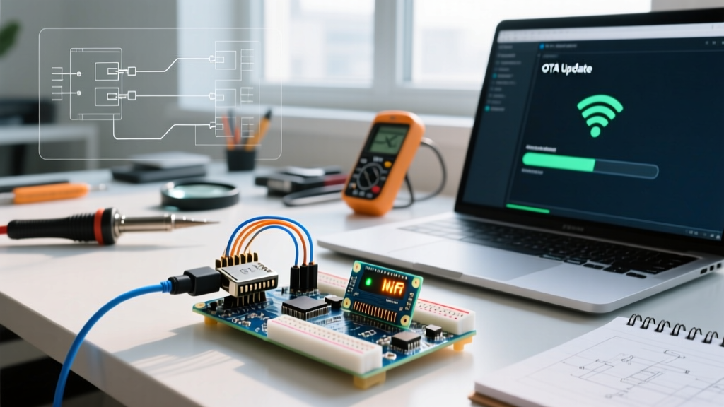
The ultimate workflow optimization is eliminating the USB cable. Flashing firmware via USB takes 15-30 seconds per iteration and requires physical access to the device. Over-The-Air (OTA) updates push compiled binaries over the local Wi-Fi network in 3-5 seconds.
Step-by-Step OTA Integration
- Include the native OTA library:
#include <ArduinoOTA.h>. - In your
setup()function, initialize the OTA service after establishing the Wi-Fi connection. Set a hostname (e.g.,ArduinoOTA.setHostname("Flux-Sensor-Node-01");) and an optional password for security. - Crucially, add
ArduinoOTA.handle();at the very top of yourloop()function. If this is blocked bydelay()or synchronous sensor reads, the board will not respond to upload requests.
For deep dives into OTA partition schemes and secure update protocols, the Espressif Arduino-ESP32 Core Repository provides the most authoritative and up-to-date technical documentation on ESP32 memory partitioning.
Hardware Edge Cases & Power Pitfalls
Software workflows fail when the underlying hardware is unstable. When connecting Wi-Fi modules, power delivery is the number one cause of silent failures and random reboots.
The 240mA TX Spike
When the ESP32 or ESP8266 transmits data over Wi-Fi, the internal RF amplifier engages, causing a sudden current spike of up to 240mA to 300mA. If you are powering your node via a standard USB-to-Serial adapter that only supplies 500mA, and your board uses a cheap linear regulator (like the AMS1117), the voltage will droop below the 3.3V threshold. This triggers a brownout reset.
Actionable Hardware Fixes:
- Decoupling Capacitors: Always solder a 100µF electrolytic capacitor and a 0.1µF ceramic capacitor directly across the 3.3V and GND pins of the Wi-Fi module. This provides the instantaneous current required during TX spikes.
- Logic Level Shifting: If you are forced to interface a 5V Arduino Uno with a 3.3V ESP-01 module via UART, never connect the TX/RX pins directly. The 5V logic will degrade the ESP8266's GPIO pins over time. Use a bidirectional logic level shifter (e.g., BSS138 MOSFET-based or CD4050 buffer) to safely bridge the voltage domains.
- Disable Brownout Detector (Use with Caution): If you are operating on the edge of your power supply's limits and experiencing boot loops, you can disable the ESP32's brownout detector in code via
#include <soc/soc.h>andWRITE_PERI_REG(RTC_CNTL_BROWN_OUT_REG, 0);. However, the correct engineering solution is to upgrade your power supply to a dedicated 5V/2A buck converter.
Summary: Build Faster, Debug Smarter
Mastering how to connect Wi-Fi to Arduino in a modern context means looking beyond the basic WiFi.begin() function. By selecting the right native hardware (like the Uno R4 WiFi or ESP32), shifting from HTTP to MQTT, utilizing PlatformIO for dependency management, and implementing OTA updates, you transform a frustrating hardware debugging session into a streamlined, professional software engineering workflow. For further silicon specifications and RF certification details, consult the Espressif ESP32 Official Product Page.