
Decoding the Foundation: What Does pinMode Do in Arduino?
When makers first transition from breadboarding simple circuits to programming microcontrollers, one of the most fundamental questions they ask is: what does pinMode do in arduino? At its most basic level, the pinMode() function configures a specific General Purpose Input/Output (GPIO) pin to behave either as an input or an output. However, as the maker ecosystem has evolved in 2026 to include advanced architectures like the Renesas RA4M1 (Arduino Uno R4), ESP32-S3, and Raspberry Pi RP2040, the hardware reality behind this simple function has become vastly more complex.
Under the hood, pinMode() manipulates specific hardware registers. On a classic ATmega328P, it toggles bits in the Data Direction Register (DDRx). On an ARM Cortex-M0+ like the RP2040, it configures the SIO (Single-Cycle IO) block and pad control registers. Understanding these hardware-level differences is critical for cross-board compatibility, preventing silicon damage, and ensuring reliable sensor readings.
Architecture Compatibility Matrix
Not all Arduino-compatible boards interpret pinMode() parameters identically. A sketch that compiles and runs perfectly on an Uno R3 might exhibit silent failures or erratic behavior on an ESP32 or Nano 33 IoT. Below is a compatibility matrix detailing how different architectures handle GPIO configuration modes.
| Architecture | Board Example | INPUT_PULLUP | INPUT_PULLDOWN | Open-Drain Support | Logic Level |
|---|---|---|---|---|---|
| AVR (8-bit) | Arduino Uno R3 | Native (~30kΩ) | Unsupported (Fails silently) | Via Port Manipulation | 5V |
| ARM Cortex-M4 | Arduino Uno R4 Minima | Native (Configurable) | Native | Native (OUTPUT_OPEN_DRAIN) | 5V |
| Xtensa LX7 | ESP32-S3 | Native (~45kΩ) | Native (~45kΩ) | Native | 3.3V |
| ARM Cortex-M0+ | Raspberry Pi Pico W | Native (~50kΩ) | Native (~50kΩ) | Native | 3.3V |
| ARM Cortex-M4F | Arduino Nano 33 IoT | Native | Native | Native | 3.3V |
The Hardware Reality of Internal Resistors
The most common use case beyond basic INPUT and OUTPUT is INPUT_PULLUP. This mode activates an internal resistor connecting the GPIO pin to the logic high voltage (VCC), eliminating the need for external resistors when wiring pushbuttons or mechanical switches. But what happens when you measure the actual current draw across different boards?
Resistance Variations Across Silicon
- ATmega328P (AVR): The internal pull-up is not a precise resistor. According to the Microchip datasheet, it ranges between 20kΩ and 50kΩ. At 5V, this means a depressed button will draw between 0.1mA and 0.25mA to ground.
- ESP32-S3 (Xtensa): Espressif's GPIO matrix utilizes a weaker internal pull-up, typically around 45kΩ. If you are designing a low-power battery-operated sensor node, this higher resistance is beneficial for sleep-state current conservation.
- RP2040 (Pico): The RP2040 pad control registers configure pull-ups at approximately 50kΩ to 60kΩ.
Expert Insight: If you are using internal pull-ups for an I2C bus (which is generally discouraged for high-speed modes due to bus capacitance), the 45kΩ resistance on an ESP32 will result in excessively slow rise times on the SDA/SCL lines, causing I2C timeouts at 400kHz. Always use external 4.7kΩ pull-up resistors for I2C, regardless of the pinMode() capabilities.
The INPUT_PULLDOWN Trap: A Silent Compatibility Killer
One of the most frequent edge cases in cross-platform Arduino development involves the INPUT_PULLDOWN mode. Modern 3.3V architectures like the ESP32 and RP2040 feature hardware pull-down resistors, allowing a pin to default to LOW when a switch is open.
Warning: The classic AVR architecture (ATmega328P, ATmega2560) does not possess hardware pull-down resistors. If you compile
pinMode(2, INPUT_PULLDOWN);for an Arduino Uno R3, the Arduino IDE will not throw a compilation error. The compiler will silently ignore the pull-down request, leaving the pin in a High-Impedance (High-Z) floating state. This leads to phantom interrupts and erratic digital readings.
To maintain strict compatibility across both legacy AVR and modern ARM boards, developers must use INPUT_PULLUP and invert their logic in software (e.g., treating LOW as the active/pressed state).
Analog Pins and the ADC Multiplexer Myth
A pervasive myth in the maker community is that you must explicitly declare pinMode(A0, INPUT); before calling analogRead(A0). This is fundamentally incorrect and stems from a misunderstanding of how the Analog-to-Digital Converter (ADC) multiplexer operates.
When you call analogRead(), the microcontroller's hardware automatically routes the selected analog pin through an internal multiplexer directly to the ADC sample-and-hold circuit. The digital data direction register (DDR) is bypassed. In fact, explicitly setting an analog pin to OUTPUT and then attempting an analogRead() can yield inaccurate results, as the digital output driver will fight the incoming analog voltage, potentially damaging the silicon if the external voltage exceeds the driven logic level.
For optimal ADC accuracy on boards like the Arduino Nano 33 IoT (SAMD21), leave analog pins in their default High-Z state or explicitly set them to INPUT to ensure the digital output buffers are tri-stated, reducing digital noise injection into the ADC reading.
Edge Cases and Hardware Failure Modes
Misunderstanding what pinMode() does at the silicon level can lead to catastrophic hardware failure. Below are specific failure modes tied to GPIO configuration:
1. The ESP32 Strapping Pin Boot Loop
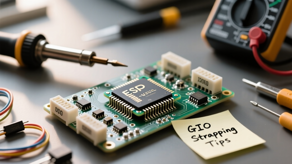
The ESP32 utilizes specific GPIO pins (e.g., GPIO0, GPIO3, GPIO12) as 'strapping pins' to determine boot modes during reset. If your circuit design includes a pull-down resistor on GPIO0, or if you configure pinMode(0, OUTPUT) and drive it LOW during the boot sequence, the ESP32 will enter UART bootloader mode instead of executing your sketch. Always consult the Espressif GPIO documentation to identify strapping pins before assigning them as standard outputs.
2. 5V Tolerance and ESD Diode Destruction
When migrating from a 5V Arduino Uno to a 3.3V Raspberry Pi Pico W, makers often reuse existing 5V sensor circuits. If you set pinMode(7, INPUT); on the RP2040 and feed it a 5V digital signal from a legacy sensor, you will forward-bias the internal ESD protection diodes. The RP2040 datasheet specifies an absolute maximum voltage of VIO + 0.3V. Exceeding this will inject current into the 3.3V rail, potentially brown-out resetting the MCU or permanently destroying the GPIO pad. Always use a logic level shifter or a simple voltage divider when bridging 5V and 3.3V domains.
3. Sourcing Too Much Current on OUTPUT
The pinMode(pin, OUTPUT) command configures the pin to source or sink current, but it does not limit the current. A classic AVR pin can source up to 20mA safely (absolute max 40mA). Connecting an LED directly to an OUTPUT pin without a current-limiting resistor will cause the LED to draw excessive current, dropping the voltage of the entire VCC rail and degrading the microcontroller's internal bond wires over time. Always calculate and place a series resistor (e.g., 220Ω for a standard red LED at 5V).
Advanced Modes: Open-Drain Outputs
For advanced bus protocols like CAN or specialized I2C implementations, standard push-pull outputs are insufficient. Modern Arduino cores (specifically for STM32 and ESP32) support OUTPUT_OPEN_DRAIN. In this mode, the microcontroller can pull the line to ground (LOW) but cannot drive it HIGH. Instead, it releases the line (High-Z), allowing an external pull-up resistor to bring the bus HIGH. This prevents bus contention if multiple masters attempt to drive the line simultaneously.
Summary Checklist for Cross-Board Compatibility
To ensure your pinMode() configurations remain robust across the fragmented Arduino ecosystem of 2026, follow this checklist:
- Never rely on INPUT_PULLDOWN for AVR: Use external resistors or invert logic with INPUT_PULLUP.
- Tri-state Analog Pins: Do not use
OUTPUTon pins designated foranalogRead(). - Verify Voltage Domains: Check logic level tolerance before setting
INPUTon 3.3V MCUs connected to 5V peripherals. - Map Strapping Pins: Avoid using boot-critical pins as standard outputs on ESP32 and SAMD architectures.
- Consult the Datasheet: The official Arduino language reference provides the baseline, but the silicon manufacturer's datasheet (such as the RP2040 Datasheet) dictates the absolute electrical limits.
Understanding the hardware reality behind pinMode() transforms you from a sketch-copying hobbyist into a capable embedded systems engineer, ready to design robust, cross-compatible hardware architectures.