
Decoding the ZS-040 Breakout Architecture
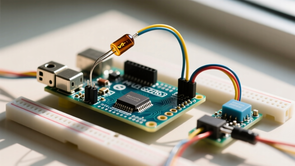
The ZS-040 is one of the most ubiquitous, budget-friendly Real Time Clock (RTC) breakout boards in the maker ecosystem. While often listed generically online, a genuine ZS-040 board is characterized by its specific silkscreen layout, featuring the DS3231 high-precision RTC chip, an AT24C32 32Kbit I2C EEPROM, a CR2032 coin cell battery holder, and a 5-pin header (GND, VCC, SDA, SCL, SQW/INT). However, its low cost comes with specific hardware design choices that create compatibility hurdles when interfacing with modern microcontrollers in 2026.
Unlike bare DS3231 chips, the ZS-040 breakout includes onboard 4.7kΩ pull-up resistors on the SDA and SCL lines, tied directly to the VCC pin. Furthermore, it includes a battery charging circuit designed for LIR2032 rechargeable cells. When adapting this board for an Arduino Uno, an ESP32-S3, or a Raspberry Pi Pico 2 (RP2350), understanding these architectural quirks is the difference between a reliable datalogger and a fried GPIO pin.
The CR2032 Charging Circuit Hazard (Mandatory Modification)
Before wiring the ZS-040 to any microcontroller, you must address a critical safety flaw in its default design. The board includes a charging circuit consisting of a surface-mount diode (typically a 1N4148 or similar Schottky) and a 200Ω resistor. This circuit attempts to trickle-charge the coin cell battery when VCC is powered.
⚠️ SAFETY WARNING: Most makers use standard CR2032 primary lithium cells, which are strictly non-rechargeable. Forcing a charge current into a primary CR2032 will cause internal gas buildup, leading to battery swelling, leakage of corrosive lithium hydroxide, and potentially violent rupture.
Step-by-Step Disarmament
To make the ZS-040 safe for standard CR2032 batteries, you must disable the charging path. You only need to break one component in the series:
- Locate the Diode: Find the small SMD diode near the battery holder, usually marked with a band indicating the cathode.
- Snip or Desolder: Using flush cutters, carefully snip the diode in half. Alternatively, apply flux and use a soldering iron to lift it off the pad.
- Verify with a Multimeter: Set your multimeter to continuity mode. Place one probe on the VCC pin and the other on the positive terminal of the battery holder. There should be no continuity (OL).
Leaving the 200Ω resistor in place is harmless once the diode is removed, as the circuit is now open. For a comprehensive look at the DS3231 power management specifications, refer to the Analog Devices DS3231 Datasheet.
Microcontroller Voltage Compatibility Matrix
The DS3231 IC itself operates safely between 2.3V and 5.5V. However, the ZS-040 breakout board's I2C logic levels are dictated by whatever voltage you feed into the VCC pin, due to the onboard 4.7kΩ pull-up resistors.
| Microcontroller | Native Logic | ZS-040 VCC Input | Direct I2C Connection? | Required Action |
|---|---|---|---|---|
| Arduino Uno R3 / R4 | 5.0V | 5.0V | Yes | None. Direct wiring is safe. |
| Arduino Nano (ATmega328P) | 5.0V | 5.0V | Yes | None. Direct wiring is safe. |
| ESP32 / ESP32-S3 | 3.3V | 3.3V | Yes | Power VCC with 3.3V. Ensure ESP32 internal pull-ups are disabled in code. |
| Raspberry Pi Pico (RP2040/RP2350) | 3.3V | 3.3V | Yes | Power VCC with 3.3V. Use GPIO pins that support I2C. |
| Teensy 4.1 | 3.3V | 3.3V | Yes | Power VCC with 3.3V. |
| Arduino Nano 33 BLE | 3.3V | 3.3V | Yes | Power VCC with 3.3V. Note: 5V pin on this board is output only. |
The 5V-to-3.3V Logic Level Trap
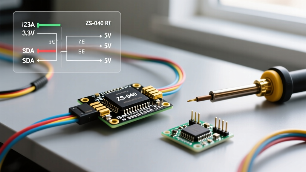
A common and destructive mistake is powering the ZS-040 VCC pin with 5V (to ensure the backlight or other 5V peripherals work) while connecting the SDA/SCL lines directly to a 3.3V ESP32. Because the ZS-040 pulls the I2C lines up to VCC (5V), this sends 5V directly into the ESP32's 3.3V-tolerant GPIO pins. While some ESP32 pins have clamping diodes, sustained 5V exposure will degrade the silicon and eventually destroy the microcontroller.
The Fix: If you must run the ZS-040 at 5V on a mixed-voltage bus, you must use a bidirectional logic level converter (like a BSS138-based module) between the ZS-040 and the 3.3V microcontroller. Alternatively, simply power the ZS-040 VCC with 3.3V; the DS3231 will function perfectly, and the I2C lines will safely idle at 3.3V.
I2C Address Mapping and Bus Collisions
The ZS-040 hosts two distinct I2C devices on the same bus. Understanding their addressing is critical for sketch compilation and bus scanning.
- DS3231 RTC: Hardcoded to
0x68. This cannot be changed. - AT24C32 EEPROM: Defaults to
0x57on the ZS-040. The board features three unbridged jumper pads (A0, A1, A2). By default, these are pulled high to VCC via 10kΩ resistors. If you solder-bridge these pads to ground, you can alter the EEPROM address down to0x50, allowing up to 8 ZS-040 modules on a single Arduino Wire bus.
Edge Case - Bus Capacitance: According to the NXP I2C Bus Specification, the maximum allowable bus capacitance is 400pF. The ZS-040's 4.7kΩ pull-ups are relatively strong. If you daisy-chain more than three ZS-040 modules, the combined trace capacitance and pin capacitance will cause I2C signal rise times to degrade, resulting in corrupted EEPROM writes. For multi-node setups, remove the 4.7kΩ pull-ups on all but one ZS-040 board.
Software Library Compatibility and Memory Footprint
Choosing the right library is vital, especially when pairing the ZS-040 with memory-constrained MCUs like the ATtiny85 or when optimizing ESP32 deep-sleep routines.
| Library Name | Maintainer | Flash Footprint | RAM Usage | Best Use Case |
|---|---|---|---|---|
| RTClib | Adafruit | ~2,800 bytes | ~150 bytes | Standard Arduino Uno/Mega projects; excellent DateTime parsing. |
| uRTCLib | Naguissa | ~1,400 bytes | ~40 bytes | ATtiny85, low-memory dataloggers, battery-operated nodes. |
| MD_DS3231 | MajicDesigns | ~2,100 bytes | ~80 bytes | Projects requiring advanced alarm and square-wave control. |
EEPROM Write Wear-Leveling
The AT24C32 EEPROM on the ZS-040 is rated for 1 million write cycles. A common beginner mistake is writing the current timestamp to the EEPROM every second inside the loop() function. This will destroy the EEPROM memory cells in roughly 11 days. Always implement a software wear-leveling algorithm or only log data to the EEPROM at intervals of 5 minutes or greater. Furthermore, the AT24C32 utilizes a 32-byte page write buffer; structuring your I2C writes in 32-byte chunks drastically reduces the I2C bus transaction time and saves battery life.
Advanced Interrupts: Utilizing the SQW Pin
The 5th pin on the ZS-040 header is labeled SQW/INT. This pin is directly tied to the DS3231's square wave/interrupt output. By default, many tutorials ignore this pin, relying on the microcontroller to constantly poll the RTC via I2C to check the time. This keeps the microcontroller awake, draining power.
For ultra-low-power compatibility (e.g., ESP32 deep sleep or ATmega328P power-down mode), configure the DS3231 to output a 1Hz square wave or trigger an interrupt on Alarm 1. Connect the SQW pin to a hardware interrupt pin on your Arduino (e.g., Pin 2 on an Uno, or an RTC_GPIO pin on an ESP32). When the alarm triggers, the SQW pin pulls low, waking the microcontroller instantly. This technique reduces system power consumption from 15mA down to roughly 12µA, making the ZS-040 viable for multi-year solar-powered environmental sensors.