
Mastering the Physical Connection: USB, UART, and Beyond
Understanding how to connect Arduino to computer environments is the foundational step for any embedded systems project. While plugging in a USB cable seems trivial, the reality of modern microcontroller development involves navigating USB-C power delivery handshakes, virtual COM port (VCP) driver signatures, and bootloader synchronization. Whether you are configuring a native USB Arduino Uno R4 WiFi, a clone Elegoo Nano relying on a CH340 serial converter, or an ESP32 dev board, this configuration guide will walk you through the exact hardware, software, and driver requirements for a flawless connection in 2026.
Hardware Interface Matrix
Not all Arduino boards communicate identically. The physical interface dictates the driver requirements and maximum serial throughput. Below is a breakdown of the most common connection architectures you will encounter.
| Board Architecture | Physical Connector | USB-to-Serial IC | Max Baud Rate | Driver Requirement |
|---|---|---|---|---|
| Arduino Uno R4 Minima/WiFi | USB-C (Data) | Native Renesas RA4M1 | 12 Mbps (Native) | None (OS Native) |
| Arduino Nano Every | Micro-USB | Native ATmega4809 | 115,200 bps | None (OS Native) |
| Clone Uno R3 (Elegoo/HiLetgo) | USB-B (Square) | WCH CH340G / CH340C | 2 Mbps | CH341SER Required |
| Arduino Nano (Classic/Clone) | Mini-USB / USB-C | FTDI FT232RL / CH340 | 3 Mbps (FTDI) | FTDI VCP / CH341SER |
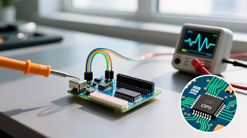
| ESP32 DevKitC V4 | Micro-USB / USB-C | Silicon Labs CP2102 | 921,600 bps | CP210x VCP Required |
Step 1: The Physical Layer and Cable Selection
The most frequent point of failure when figuring out how to connect Arduino to computer setups is the cable itself. The market is flooded with 'charge-only' cables that lack the internal D+ and D- data lines required for serial communication.
Critical Warning: If your Arduino powers on (the ON LED illuminates) but no COM port appears in your device manager, you are almost certainly using a charge-only cable. Discard it and use a certified data cable like the UGREEN USB-C to USB-A 3.1 or Cable Matters USB-B Data Cable. A proper data cable will trigger the OS hardware enumeration chime within 2 seconds of insertion.
For boards utilizing USB-C (like the Arduino Uno R4 or modern ESP32-S3 boards), ensure your computer's USB-C port supports data transfer and isn't restricted to power delivery (PD) only, which is common on some ultra-thin laptops and tablet hubs.
Step 2: Driver Configuration and OS Handshakes
Native USB boards (like the Uno R4 or Leonardo) emulate a serial port directly via the microcontroller's hardware USB peripheral. However, legacy boards and budget clones rely on bridge chips. Here is how to configure the drivers for the big three bridge ICs.
1. WCH CH340 / CH341 (Common on Clones)
The CH340 is ubiquitous in 2026 due to its low cost. However, Windows 11's Core Isolation and Memory Integrity features frequently block older, unsigned versions of the CH340 driver.
- Windows: Download the official CH341SER.EXE (version 3.5 or higher) from the WCH website or your board vendor. Run the installer as Administrator. If Windows Defender SmartScreen flags it, verify the digital signature is from 'WCH' before bypassing.
- macOS Sequoia: Modern macOS versions include a native Apple driver for the CH340. If you experience kernel panics or dropped packets, uninstall the legacy 'CH34xVCPDriver.pkg' and rely on the native AppleUSBSerial support.
- Linux (Ubuntu/Debian): The
ch341-uartmodule is built into the kernel. No manual installation is required.
2. Silicon Labs CP2102 / CP2104 (Common on ESP32)
The CP210x series offers higher baud rates and is standard on Espressif dev boards.
- Download the CP210x Universal Windows Driver from the Silicon Labs VCP Driver page.
- Extract the ZIP file, open Device Manager, locate 'Other Devices' -> 'CP2102 USB to UART Bridge', right-click, and select 'Update driver' -> 'Browse my computer' -> point to the extracted folder.
3. FTDI FT232RL (Premium Clones & Pro Boards)
FTDI chips are the gold standard for reliability. You can grab the latest VCP drivers directly from the FTDI Chip VCP Drivers portal. On Windows, these usually install automatically via Windows Update, but manual installation ensures you get the latest latency timer configurations.
Step 3: Arduino IDE 2.3.x Port Mapping
With the physical connection established and drivers loaded, open the Arduino IDE (version 2.3.x or newer). The modern IDE utilizes a background daemon (arduino-cli) to enumerate ports.
- Navigate to Tools > Board and select your exact hardware (e.g., Arduino Uno R4 Minima or Arduino AVR Boards -> Nano).
- Navigate to Tools > Port. You should see a port labeled with your board name (e.g.,
COM4 (Arduino Uno R4)on Windows or/dev/cu.usbmodem101on macOS). - If the port is missing, click the Select Board prompt on the top toolbar, which opens the hardware discovery matrix. This matrix actively polls USB VID/PID (Vendor ID / Product ID) to match your physical device.
For comprehensive setup instructions, refer to the official Arduino Getting Started documentation.
Advanced Configuration: UART/FTDI Serial Bypass
Sometimes, you cannot connect via standard USB. Perhaps you are programming an ATmega328P-PU on a breadboard, or your Arduino's onboard USB-Serial IC has failed. In these cases, you must use an external USB-to-TTL Serial Adapter (FTDI programmer).
Wiring the UART Bypass
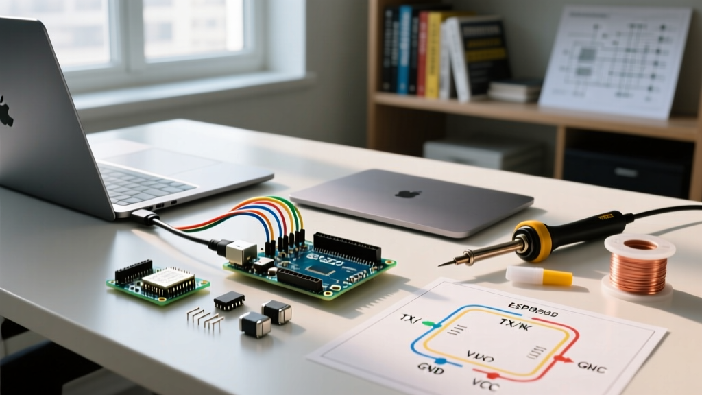
Connecting via UART requires crossing the data lines and managing the DTR (Data Terminal Ready) reset signal.
- TX to RX: Connect FTDI TX to Arduino RX (Pin 0).
- RX to TX: Connect FTDI RX to Arduino TX (Pin 1).
- GND to GND: Crucial for establishing a common logic reference.
- VCC: Set the FTDI jumper to 5V (for standard Unos) or 3.3V (for 3.3V Pro Minis). Do not connect VCC if the Arduino is already powered externally.
The Auto-Reset Hack: To allow the IDE to automatically trigger the bootloader without manually pressing the reset button, wire a 0.1µF ceramic capacitor between the FTDI's DTR pin and the Arduino's RESET pin. This mimics the behavior of the onboard serial capacitor, pulling the reset line low for exactly 100ms when the IDE opens the COM port to upload.
Troubleshooting Matrix: Edge Cases and Fixes
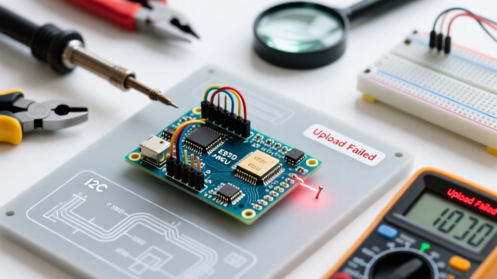
Even with perfect hardware, software edge cases will occur. Use this diagnostic matrix to resolve the most stubborn connection and upload failures.
| Symptom / Error Code | Root Cause Analysis | Exact Fix / Configuration |
|---|---|---|
| Port is Grayed Out in IDE | OS recognizes USB device but lacks VCP driver, or port is locked by another process. | Close Cura, PrusaSlicer, or any 3D printer software that auto-polls serial ports. Install correct VCP driver. |
avrdude: stk500_recv(): programmer is not responding |
Wrong board selected, wrong bootloader (e.g., Nano Old vs New), or TX/RX lines blocked. | Verify Tools > Processor. For Nano clones, select 'ATmega328P (Old Bootloader)'. Disconnect pins 0 and 1 during upload. |
Permission denied: '/dev/ttyACM0' (Linux) |
Current user lacks permission to access the serial dialout group. | Run sudo usermod -a -G dialout $USER in terminal, then reboot or log out/in to apply group changes. |
| ESP32 'Connecting...' Timeout | Auto-reset circuit on clone ESP32 boards fails to pull GPIO0 low for bootloader entry. | Hold the physical 'BOOT' button on the ESP32 when the IDE outputs 'Connecting...', then release after 2 seconds. |
| Unknown USB Device (Port Reset Failed) | USB hub power starvation or native USB firmware crash (common on Leonardo/Micro). | Plug directly into motherboard rear I/O. Double-tap the physical reset button to force bootloader mode, then quickly hit Upload. |
Final Configuration Advice
Mastering how to connect Arduino to computer systems is less about the physical act of plugging in a cable and more about understanding the software stack bridging your hardware to the IDE. Always verify your cable's data integrity first, ensure your VCP drivers are signed and compatible with modern OS security features, and utilize the IDE's hardware discovery matrix to confirm VID/PID matching. By following these configuration protocols, you will eliminate 99% of serial communication bottlenecks and focus on what matters: writing robust embedded code.